


EN
|
14
Bosch Security Systems | 18 August 2005
LTC 8016/90 | Instruction Manual | Installation
4.6 Allegiant Series Switcher Data
Interface
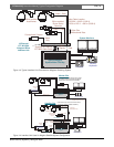
4.6.1 Allegiant Interface Configurations
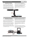
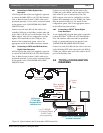
When using the Allegiant data interface protocol, up
to 31 Interface Units can be connected to a single
large Allegiant system. In this configuration, bi-
directional Bilinx communication to physical cameras
ranging from 1 to 496 is supported. In very large
systems, additional units can be interfaced to the
Allegiant via biphase data connection.
When connecting to an Allegiant system, select a data
port on the main Allegiant CPU that will be used to
communicate with the Interface Unit. The Interface
Unit provides separate interface connectors so it is able
to support both RS-232 and RS-485 Allegiant interfaces.
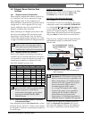
Only one port on the Interface Unit can be
used at a time. Connecting data cables to
more than one port on the Interface Unit
simultaneously could result in non-operation.
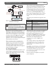
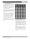
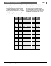
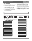
4.6.1.1 Allegiant Interface Port Selection
Based on the Allegiant model being used, select an
available CPU port from the table below. Note that it
is not possible to connect the Interface Unit cable to a
Console port provided by an Allegiant LTC 8712
Series Port Expander accessory unit.
The ALARM port requires a special cable
pinout. DO NOT USE the supplied cable for
this port connection. A cable must be
constructed by the installer, per the pinouts
shown in the CONNECTOR & CABLE
PINOUTS Section.
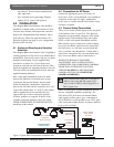
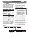
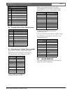
4.6.1.2 Setting the Allegiant System to Use Bilinx
Communication Mode
Using Allegiant Keyboard User Function 39, a system
keyboard operator with Level 1 Priority must configure
the Allegiant to enable the communication interface on
the selected port.
IntuiK
ey S
eries Keyboard:
From the main Allegiant screen, navigate to the User
Functions menu screen, then press [Enter User
Command]. Key in 39, then press [Enter].
L
TC 8555 or LTC 8550 Series Keyboard:
Press [USER], key in 39, then press [Enter].
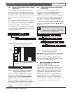
The monitor’s on-screen text will indicate the current
configuration mode, such as NO DIU OPERATION
(i.e., meaning No D
ata Interface Unit Operation) on
a non-configured system. Use the keyboard joystick
up/down to navigate through the available port
options. Enter the operator password when prompted,
and press [Enter] to select the port currently shown.
The port is now configured with the proper baud rate
and handshake settings to communicate with the
Interface Unit.
If the on-screen option reads No CTS
Operation, the CPU firmware version is older
than the revision needed for compatibility with
Bilinx communication. On Allegiant systems
sold after 1995, CPU upgrades can be done
from an external PC using a software
download approach. Older systems
(i.e., having CPU modules with a single
8-position dip switch) can be upgraded by
replacing the CPU module. Contact the
nearest Bosch Security Systems Sales
Representative or Tech Support specialist for
additional details on Allegiant CPU upgrades.
A system reset is required to complete the process.
Either use Keyboard User Function 15, or power
off/on the main Allegiant CPU bay. The Allegiant is
then ready to communicate with the Interface Unit.
Allegiant
Model
Supported Ports
CONSOLE PRINTER ALARM1 COM1 COM2
LTC 8100 YES NO NO NO NO
LTC 8200 YES NO NO NO NO
LTC 8300 YES YES NO NO NO
LTC 8500 YES YES YES NO NO
LTC 8600 YES YES YES YES YES
LTC 8800 YES YES YES YES YES
LTC 8900 YES YES YES YES YES
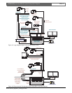
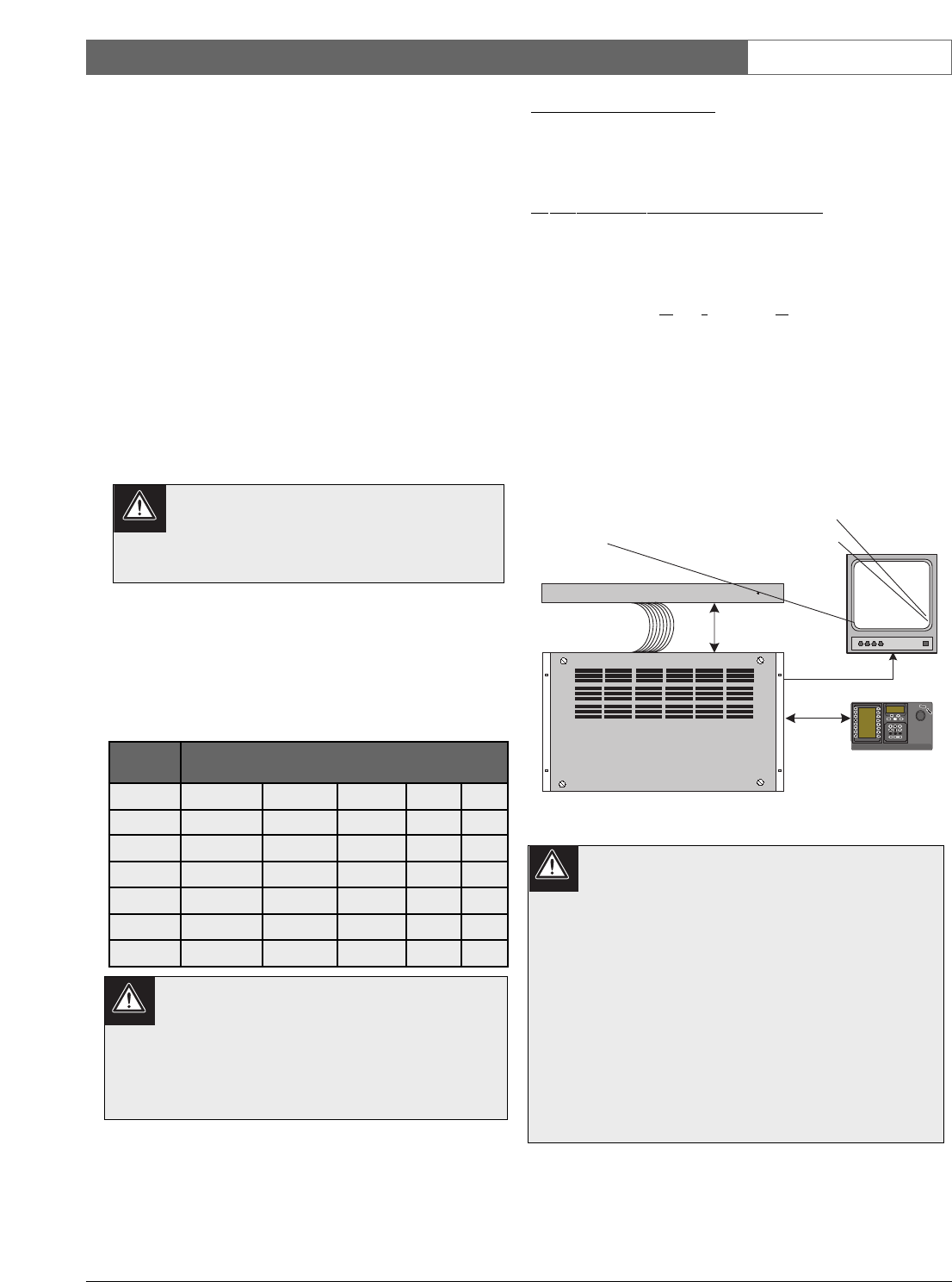
ALLEGIANT Video Matrix
BOSCH
IntuiKey
Keyboard
Typical Allegiant
System Main CPU Bay
BOSCH
POWER
Allegiant Data
Interface Protocol
LTC 8016/90
Interface Unit
1 2
3
4 5
6
7 8
9
0
Shot
Mon
Prod
Clr
BOSCH
BOSCH
001 PASSWD REQ'ED 12:00:00
NO DIU OPERATION 12-01-04
001 PASSWD REQ'ED 12:00:00
NO DIU OPERATION 12-01-04
Figure 6 Allegiant On-screen Setup Procedure for
Bilinx Operation