


EN
|
13
Bosch Security Systems | 18 August 2005
LTC 8016/90 | Instruction Manual | Installation
1 m (3 ft)
LTC 8508/01
Ribbon-to-BNC
Cable (Purchased
Separately)
PC
INPUTS
15
16
13
14
11
12
9
10
8
6
5
3
4
2
LOOPING VIDEO 1-16
. . . . . . . . . . . . . . . . .
. . . . . . . . . . . . . . . . .
7
1
RS-232
RS-485 IN
RS-485 OUT
DATA
ETHERNET
10/100 BaseT
ACTLINK
CODE
BIPHASE IN
GROUP ID
0
2
6
4
8
0
2
6
4
8
0
2
6
4
8
Connect to Video Input
Connectors on Control Unit
16 BNC
Connectors
LTC 8016 Interface Unit
BOSCH
Divar Digital Versatile Recorder
SEARCH
B
ACK
ALT
1 2 3 4 5 6 7 8 9 10 11 12 13 14 15 16LIVE
F2F1
ESC
A
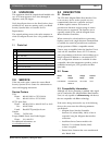
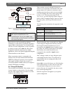
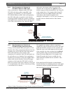
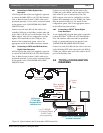
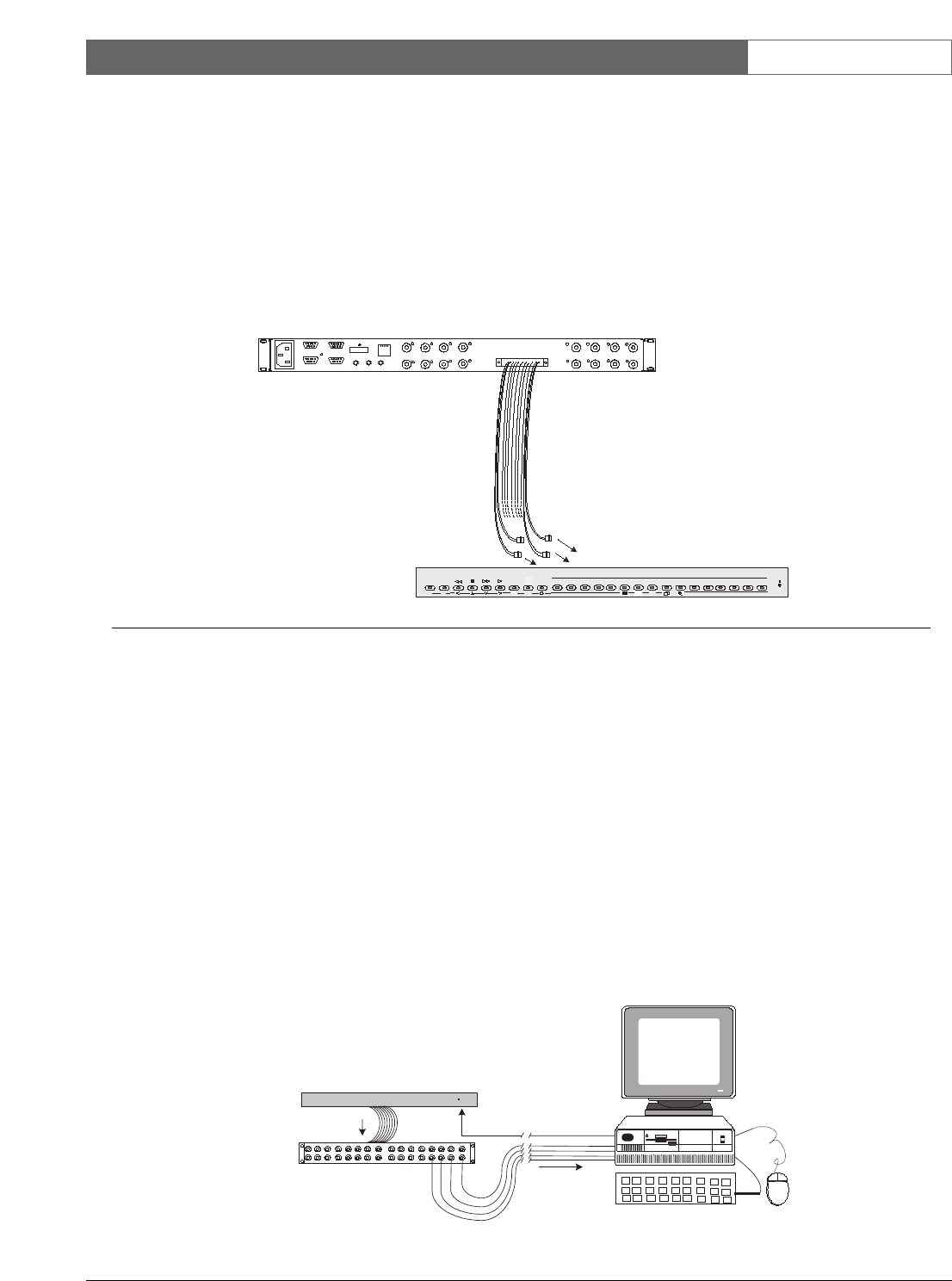
Figure 4 Typical Video Connections to Divar Series DVR Control Units
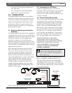
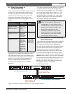
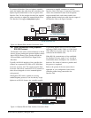
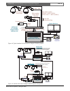
Figure 5 Video Connections to Control System Located at Remote Site
4.5.2 Video Connections to Products via
LTC 8508/01 Ribbon-to-BNC Cable
Video connections to Allegiant models LTC 8100,
LTC 8500, and other products using BNC video
connectors, can utilize the 1 m (3 ft) 16-channel
LTC 8508/01 Ribbon-to-BNC cable (sold separately).
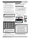
One LTC 8508 cable is required for each Interface
Unit being installed. Noting the connector orientation
and alignment tab, connect the ribbon connector end
of the cable to the Interface Unit. Attach the BNC
ends to the video inputs on the rear panel of the
controller that corresponds to the physical camera
number range previously determined by the Group ID
switch settings above. For example, if the Group ID
switches have been set to 001, the BNC ends of the
video ribbon cable should be installed in the
controller’s video inputs 1 to 16. For your convenience,
the BNC ends are marked with the video channel
number.
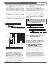
4.5.3 Video Connections to Products via
LTC 8807/00 Video Interconnect Panel
If using a rack-mountable BNC patch panel, or if the
Interface Unit will be remoted some distance from the
controller unit, an LTC 8807/00 Video Interconnect
Panel (sold separately) can be used for video
connections to a controller. Each LTC 8807 panel can
be used with up to two Interface Units, supporting a
maximum of 32 cameras. Connect the supplied video
ribbon cable from the Interface Unit into the upper
connector on the back of the LTC 8807 for the first
block of 16 cameras. The lower connector is only used
if a second Interface Unit will be connected, providing
a second block of 16 cameras.
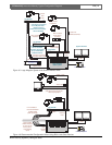
User-supplied coax jumper cables are required to
complete the video connections between the LTC 8807
panel and the BNC connectors on the controller unit.
Attach the coax to the video inputs on the rear panel
of the controller bay, that correspond to the physical
camera number range previously determined by the
Group ID switch settings above. For example, if the
Group ID switches have been set to 001, the coax
cables should be installed into the controller’s video
inputs 1 to 16.
If the control unit will be located at a remote distance
from the Interface Unit, standard practices for video signal
transmission, and the associated data interface, should be
used (more details provided in the next section).
Typical Remoted DVR
or Other Biphase-
enabled Controller
BOSCH
POWER
Interface
Data
Customer-supplied
Video Coax
LTC 8807/00 Interconnect Panel
(sold separately) for use with up to
two (2) LTC 8016 units
Video
Signals
LTC 8016/90
Interface Unit
Supplied 16-Channel
LTC 8809 Video Cable
Follow Standard
Practices for Remoting
Coax & Data Cables