


EN
|
11
Bosch Security Systems | 18 August 2005
LTC 8016/90 | Instruction Manual | Installation
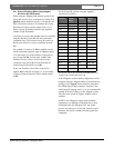
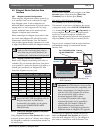
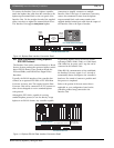
4.4.2 Switch Settings When Interfacing to Biphase
Controller Devices
When using a biphase data interface, the Group
ID switches must be set to correspond to a block
of 16 logical camera numbers between 1-16 and
9985-9999. Since each block consists of 16 numbers,
the Group ID number for these cameras range from
1 to 625. The Group ID number selected must not
duplicate Group ID numbers already used.
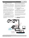
The Interface Unit is set to 901 by default, and no
change is required when only one Interface Unit is
used in a system for cameras 1 to 16. Otherwise, use
the supplied screwdriver to set the Group ID
to correspond to the logical camera number range
shown in the table below. For larger systems, refer
to APPENDIX A for additional Group ID switch
settings.
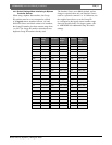
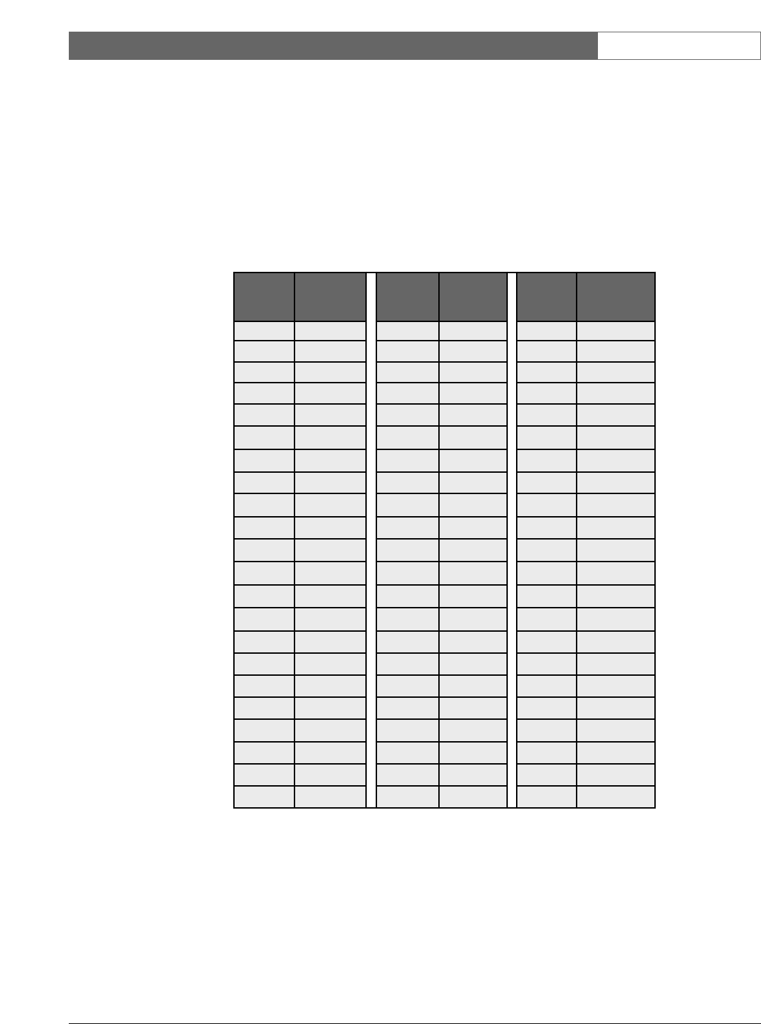
Group ID
Switches
Camera
Number
Range
Group ID
Switches
Camera
Number
Range
Group ID
Switches
Camera
Number
Range
001 1 to 16 023 353 to 368 045 705 to 720
002 17 to 32 024 369 to 384 046 721 to 736
003 33 to 48 025 385 to 400 047 737 to 752
004 49 to 64 026 401 to 416 048 753 to 768
005 65 to 80 027 417 to 432 049 769 to 784
006 81 to 96 028 433 to 448 050 785 to 800
007 97 to 112 029 449 to 464 051 801 to 816
008 113 to 128 030 465 to 480 052 817 to 832
009 129 to 144 031 481 to 496 053 833 to 848
010 145 to 160 032 497 to 512 054 849 to 864
011 161 to 176 033 513 to 528 055 865 to 880
012 177 to 192 034 529 to 544 056 881 to 896
013 193 to 208 035 545 to 560 057 897 to 912
014 209 to 224 036 561 to 576 058 913 to 928
015 225 to 240 037 577 to 592 059 929 to 944
016 241 to 256 038 593 to 608 060 945 to 960
017 257 to 272 039 609 to 624 061 961 to 976
018 273 to 288 040 625 to 640 062 977 to 992
019 289 to 304 041 641 to 656 063 993 to 1008
020 305 to 320 042 657 to 672 064 1009 to 1024
021 321 to 336 043 673 to 688
022 337 to 352 044 689 to 704