


D9412GV3/D7412GV3 | Operation and Installation Guide | 12.0 SDI Devices
.
Bosch Security Systems, Inc. | 10/10 | F01U143070-03 60
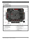
12.4 D9210B Wiegand Control Interface
Module
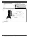
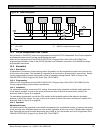
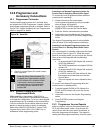
The Bosch Security Systems, Inc. D9210B Wiegand
Control Interface Module is a four-wire powered
device providing connections for an access door point
and door strike. The D9412GV3 can supervise eight
Wiegand Control Modules, the D7412GV3 can
supervise two. Each D9210B supports one door to
control access. Programming allows each access
door to be configured independently.
12.4.1 Access
Using Wiegand style cards or tokens, the D9210B can
allow access for up to 996 cards or tokens on the
D9412GV3, and up to 396 on the D7412GV3. User
access authority can be configured to restrict access
to certain doors or to certain periods of time. The
reading of access cards, in addition to granting
access, can control whether the system disarms.
Used with the D9412GV3, the D9210B recognizes
249 master users by user name, passcode, and
access authority. The D9210B recognizes 99 master
users when used with the D7412GV3. Each master
user supports three sub-users with unique cards or
tokens having the same access level as the master
user.
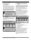
12.4.2 Switch Settings
Switches on the D9210B assign a unique address
(1 to 8) to each module. Table 23 shows the correct
switch setting for each D9210B address.
Table 23: Address Switch Settings for
Access Control Module
DIP Switch Settings
Door Module
Addresses
1 2 3 4
1
5
2
6
2
1 ON ON ON ON ON
2 OFF ON ON ON ON
---------------D7412GV3 Maximum---------------
3 ON OFF ON ON ON
4 OFF OFF ON ON ON
5 ON ON OFF ON ON
6 OFF ON OFF ON ON
7 ON OFF OFF ON ON
8 OFF OFF OFF ON ON
1
Switch 4, Fail Safe Mode:
ON = If SDI bus fails, relay energizes.
OFF = If SDI bus fails, relay de-energizes.
2
Switches 5 and 6 must remain in the ON position.
12.5 SDI Addresses 88 and 92
SDI Addresses 88 and 92 are available with the
D9412GV3 and D7412GV3 Control Panels and are
used for several different applications. Only one
device can be assigned to SDI Address 88 at a time.
Likewise, only one device can be assigned to SDI
Address 92 at a time.
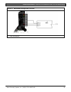
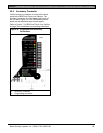
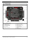
12.5.1 D9133DC Direct Connect Programming
Module
Use the D9133DC Direct Connect Programming
Module to handle local programming of the
D9412GV3 and D7412GV3 Control Panels. In
addition, the D9133DC allows diagnostic and history
retrieval.
The D9133DC is not UL Listed, and
cannot remain connected to the system
for UL applications.
UL requires that the D9133DC be used
for programming only.
D9133DC uses SDI 88 only.
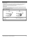
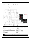
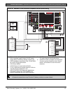
Connecting the D9133DC
1. Configure D9133DC for SDI Address 88. To
program the control panel when the reset pin is in
the unlocked position, program Enable SDI RPS
to Yes in the GV2AUX handler.
2. Connect D9133DC to Com Port 1 or Com Port 2
on the PC. The D9133DC has a DB-9 female
serial connector. A null-modem cable must be
purchased separately to connect the D9133DC to
a PC.
3. Using 0.8 mm (22 AWG) or 1.2 mm (18 AWG)
wire, connect the D9133DC SDI terminals (SDI
PWR, SDI A, SDI B, and SDI COM) to the control
panel’s SDI terminals (Terminals 29 to 32).
To send or receive the control panel’s program, place
the Reset Pin in the Locked or Unlocked position.
Locking the Reset Pin when
programming the control panel improves
the uploading and downloading times.