


D9412GV3/D7412GV3 | Operation and Installation Guide | 6.0 Power Outputs
.
Bosch Security Systems, Inc. | 10/10 | F01U143070-03 26
6.0 Power Outputs
6.1 Circuit Protection
Three self-resetting circuit breakers protect the control
panel from short circuits on the continuous and
programmable power outputs. If the control panel is
programmed for power supervision and a short circuit
occurs on one of the power outputs, the control panel
sends BATTERY LOW and BATTERY MISSING
when using Bosch Security Systems, Inc. Modem IIIa
2
communicator format. Under the same conditions
when using Contact ID communicator format, the
control panel sends Control Panel Battery Low (302)
and Control Panel Battery Missing (311).
One self-resetting circuit breaker protects:
Terminal 3: Auxiliary Power
Terminal 24: Zonex Power
A short circuit on one terminal disrupts
power to the other terminal.
Another self-resetting circuit breaker protects:
Terminal 6: Alarm Power Output
Terminal 7: Alternate Alarm Power Output
Terminal 8: Switched Auxiliary Power.
A short circuit on one of the terminals
disrupts power to the other two terminals.
The third self-resetting circuit breaker protects
Terminal 32: Power +.
UL requires any device powered from a
power output to be supervised.
UL requires that power outputs are not
shared between fire and non-fire devices
unless all devices are in conduit within
20 ft and are in the same room.
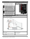
6.2 Total Available Power
The system produces up to 1.4 A of combined power
at 12.0 VDC nominal for special application use. The
outputs listed below share the available power. These
outputs are shown as red circles on the faceplate.
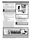
Terminal 3 - Auxiliary Power: Use this terminal to
power devices requiring continuous power.
Terminal 6 (Relay A) - Alarm Power Output:
Programmable relay normally open, power on alarm.
Terminal 7 (Relay B) - Alternate Alarm Power
Output: Programmable relay normally open, power
on alarm.
Terminal 8 (Relay C) - Switched Auxiliary Power:
Programmable relay normally closed, switches power
off when the Sensor Reset command is executed.
Terminal 24 - Zonex Power: Use this terminal to
power Zonex modules such as the D8125, D8128D,
and D8129 Modules.
Terminal 32 – SDI Power +: Use this terminal to
power serial device interface (SDI) devices such as
keypads, the D9131A Parallel Printer Interface
Module, and the D9210B Wiegand Control Interface
Module.
Accessory Connector: The D928 Dual Phone Line
Switcher connects to the accessory connector.
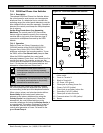
6.3 Continuous Power Output
Terminals 3, 8, 24, and 32
The continuous current draw for powered devices
connected to Terminals 3, 8, 24, and 32, and the
accessory connector must not exceed 1.4 A. Devices
powered from these outputs operate at 12.0 VDC
Nominal.
Power Restricted for Fire and Combined Fire and
Burglary Systems: Use the Fire System Power
Formula to calculate the current available for fire and
combined fire and burglary systems (refer to Section
6.4 Programmable Power Output Terminals 6, 7, and
8).