


D9412GV3/D7412GV3 | Operation and Installation Guide | 5.0 Power Supply
.
Bosch Security Systems, Inc. | 10/10 | F01U143070-03 22
5.0 Power Supply
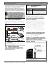
5.1 Primary Power Terminals 1 and 2
5.1.1 Primary (AC) Power Circuit
The primary source is a 16.5 VAC, 40 VA, internally-
fused transformer (Bosch Security Systems, Inc.
Model D1640). The control panel draws 200 mA when
idle and 300 mA when in an alarm state. The total
available auxiliary current is 1.4 A.
Transient suppressors and spark gaps protect the
circuit from power surges. This protection relies on
the ground connection at Terminal 10. Ensure that
you connect Terminal 10 to a proper ground. Refer to
Section 4.5 Connecting Earth Ground on page 15.
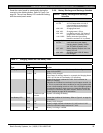
AC Power Fail
The system indicates an AC power failure when
Terminals 1 and 2 do not have power. The AC Fail
Time parameter sets the number of minutes or
seconds without AC power before the control panel
acknowledges the failure and the number of minutes
or seconds after the power returns before the control
panel acknowledges restored power. Refer to the
D9412GV3/D7412GV3 Program Entry Guide
(P/N: F01U170807) for additional information about
AC Fail Time and UL 864 requirements.
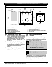
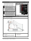
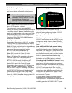
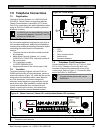
5.1.2 Installing the Transformer
Do not short-circuit the terminals of the
transformer: Shorting the terminals
opens the internal fuse, causing
permanent failure. Connect the
transformer to Terminals 1 and 2 of the
control panel before plugging it into the
power source.
1. Use 1.22 mm (18 AWG) wire (minimum) to
connect the transformer to the control panel.
The wire length should be as short as possible.
The maximum length is 15 m (50 ft). Connect the
battery and plug in the transformer.
2. Route telephone and sensor loop wiring away
from any AC conductors, including the
transformer wire.
AC wiring can induce noise and low level voltage
into adjacent wiring. Route data wiring away from
AC and telephone wiring.
Always connect the battery first and then
plug in the transformer.
3. Connect the battery. Refer to Section 5.2.2
Installing the Battery on page 22.
4. Plug the transformer into an unswitched, 120
VAC, 60 Hz power outlet only.
5. Secure the transformer to the outlet with the
screw provided.
D8004 Transformer Enclosure Required for Fire
Systems
Use the D8004 Transformer Enclosure for the D1640
Transformer in fire and combined fire and burglary
applications.
Check with the Authority Having
Jurisdiction (AHJ) about mounting
transformers on specific circuits.
5.2 Secondary Power Terminals
5.2.1 Secondary (DC) Power
A 12 V sealed lead-acid rechargeable battery (D126)
supplies secondary power for auxiliary and alarm
outputs, and powers the system during interruptions
in primary (AC) power.
Use Lead Acid Batteries Only: The
charging circuit is calibrated for lead-acid
batteries. Do not use gel-cell or nicad
batteries.
Extra Batteries Increase Back-up Time
To increase battery back-up time, connect a second
12 V battery in parallel to the first battery. Use a D122
Dual Battery Harness to ensure proper and safe
connection. Refer to the Standby Battery and Current
Rating Chart in the D9412GV3/D7412GV3 Approved
Applications Compliance Guide (P/N: F01U143069)
for battery standby time calculations.
D1218 Battery
The D1218 is a 12 V, 18 Ah battery for use in
applications requiring extended battery standby time.
Up to two D1218 batteries can be connected when
used with a D122 Dual Battery Harness.
Caution: When connecting two D1218
Batteries to the control panel, both must
have the same capacity (use two 17.2 Ah
batteries or two 18 Ah batteries).
When using two D1218 batteries, use a
separate enclosure, a D122L Dual
Battery Harness, and long leads.
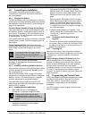
5.2.2 Installing the Battery
1. Place the battery upright in the base of the
enclosure.
2. Locate the red and black leads supplied in the
literature pack.