


D9412GV3/D7412GV3 | Operation and Installation Guide | 12.0 SDI Devices
.
Bosch Security Systems, Inc. | 10/10 | F01U143070-03 59
12.0 SDI Devices
12.1 Description
D9412GV3 and D7412GV3 Control Panels can
support a number of accessory devices from the SDI
Bus using Terminals 29 through 32. Some devices
include the D1255 and D1255B Keypads (refer to
Section 11.0 Arming Devices on page 55), D9131A
Parallel Printer Interface Module, D9210B Wiegand
Control Interface Module, DX4010i RS-232 Serial
Interface Module, ITS-DX4020-G GPRS/GSM
Communicator, and DX4020 Network Interface
Module.
For UL 864 Commercial Fire applications,
refer to Installing Combination Fire and
Intrusion Alarm Systems in the
D9412GV3/D7412GV3 Approved
Applications Compliance Guide
(P/N: F01U143069) for important
information about combination fire and
intrusion systems.
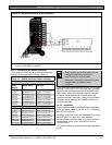
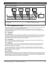
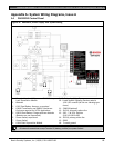
12.2 Installation
For complete installation instructions, consult the
operation and installation guide for the specific SDI
device. SDI devices connect to the control panel in
parallel (Table 21).
These devices can share power with the control panel
or be powered by a stand-alone power source.
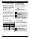
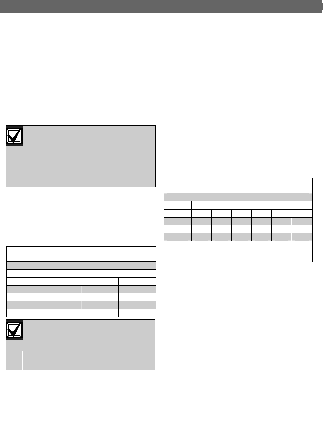
Table 21: SDI Device Connections
D9412GV3/D7412GV3 SDI Devices
Terminal Function Wire Color Function
32 POWER + Red +12.0 VDC
31 DATA BUS 1 Yellow Data
30 DATA BUS B Green Data
29 COMMON Black Common
A stand-alone power supply powering the
SDI device must also be connected to a
common terminal on the control panel.
Do not connect the earth ground for the
stand-alone power supply to Terminal 10
on the control panel.
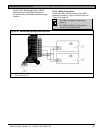
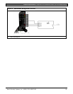
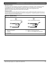
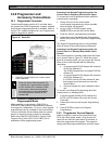
12.3 D9131A Parallel Printer Interface
Module
The Bosch Security Systems, Inc. D9131A Parallel
Printer Interface Module is a four-wire powered device
used to connect a standard parallel printer to a control
panel. D9412GV3 can supervise three printers and
the D7412GV3 can supervise one printer. A separate
D9131A Parallel Printer Interface Module is
necessary for each printer. The D9131A connects to
the printer using a standard parallel printer cable.
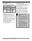
12.3.1 Switch Settings
Switches on the D9131A assign a unique address (17
to 19) for each printer. The address determines if the
printer is supervised, the area scope of the printers,
and the area to which the printer is assigned. Refer to
Printer Parameters in the D9412GV3/D7412GV3
Program Entry Guide (P/N: F01U170807) for a
complete description of addresses.
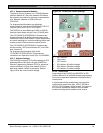
Table 22 shows the correct switch setting for each
address.
Table 22: Printer Address Switch Settings
Printer Switch
1 2 3 4
2
5 6
17 ON ON ON ON ON ON
18
1
OFF ON ON ON ON ON
19
1
ON OFF ON ON ON ON
1
D9412GV3 only.
2
Switch 4: ON = Header and form feed
OFF = No header and form feed
12.3.2 Supervision
Supervision includes:
Proper operation of the SDI bus
Proper connection of the printer cable between
the printer and the D9131A
Printer paper supply
Printer selected (on-line)
Printer power.
The control panel sends an SDI Failure Report to the
receiver if communication with the printer interface
fails. If an SDI failure occurs, SERVC PRINTER
appears at the keypad. The report to the receiver
includes the address of the troubled D9131A to
indicate which printer needs service.
If an SDI device is supervised and Terminal SDI A
becomes disconnected, the device can continue to
operate normally, depending upon environmental
conditions.