


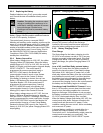
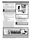
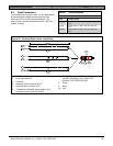
D9412GV3/D7412GV3 | Operation and Installation Guide | 8.0 On-Board Points
.
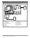
Bosch Security Systems, Inc. | 10/10 | F01U143070-03 32
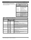
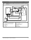
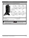
8.3 Point Parameters
The condition of on-board Points 1 to 8 is determined
by measuring the voltage across the point input
terminal and one of the common terminals. The
sensor loops must be connected and the 1 kΩ EOL
resistor in place.
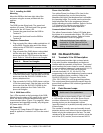
Table 9: Point Parameters
Loop Voltage Range
Open
Greater than 3.7 VDC, but less than 5.0
VDC.
Normal
Greater than 2.0 VDC, but less than 3.0
VDC.
Shorted
Greater than 0.0 VDC, but less than 1.3
VDC.
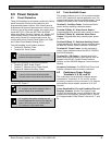
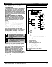
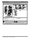
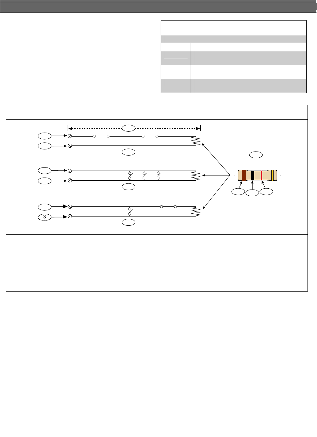
Figure 13: On-board Point Sensor Loop Wiring
1 k
4
5
6
9
7
10
1
2
3
2
3
2
8
9
10
1 - 100 Ω maximum
2 - Point input terminal
3 - Common
4 - Normally-closed contacts (NC)*
5 - Normally-open contacts (NO)
6- Combination: Normally-open contacts and
normally-closed contacts (NO/NC)
7 - P105F (Package of 8 EOL resistors) or
P105BL (Package of 8 UL Listed EOL
resistors) (P/N: 15093130-004)
8 - Brown
9 - Black
10 - Red
* UL does not allow normally-closed loops for commercial fire applications.