


©2003 Bosch Security Systems 4998138544C 05/03
130 Perinton Parkway, Fairport, NY 14450-9199 USA Operation and Installation Guide D7212G
Customer Service: (800) 538-5807; Technical Support (888) 886-6189 Page 68 of 68
P
Phone Cords ...........................................31
Phone Lines ............................................31
Dialing Format ................................... 32
Ground Start ...................................... 33
Jacks ............................................. 17, 31
Phone Line Monitor .......................... 32
Rng Indicator ..................................... 32
Seizure.......................................... 17, 31
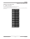
Point Address Charts .............................. 65
ZONEX 1 ........................................... 65
Point Chart Label ....................................24
Installing ............................................. 24
Points.......................................................17
Off-board .....................................17, 37
On-board ............................. 17, 24, 35
Sensor Loops ...................................... 35
Standard Features ............................... 17
POPEX ............................................ 23, 37
Wiring ................................................. 38
POPITs ............................................ 37, 38
Testing................................................. 44
Wiring .......................................... 23, 38
Power
Auxiliary ............................................. 29
Continuous Current Draw ................ 29
Primary ............................................... 25
Programmable Terminals ................... 29
Secondary ........................................... 25
Total Available .................................... 29
Power Failure ...........................................25
Power Module
Battery Discharge Schedule ................ 27
Replacing Batteries ............................. 26
Power Outputs
Alarm .................................................. 29
Alternate Alarm ................................. 29
Auxiliary ............................................. 29
Circuit Protection .............................. 29
Continuous Power Outputs Terminals
29
Fire System Power Formula ............... 30
Programmable .................................... 29
Programmable Power Outputs
Terminals ....................................... 29
Switched Auxiliary ............................. 29
Total Available Power ......................... 29
Power Supply ...........................................25
Primary Power Terminals .......................25
Printer .....................................................53
Programmer ............................................24
Connecting ........................................ 57
Programmer Connector .........................57
Programming
Standard Features ............................... 18
Programming the Panel .........................24
R
RAM IV ........................................... 18, 24
Related Documentation .........................10
Remote Account Manager ............. 18,24
Replacing Batteries ..................................26
Reports ....................................................24
Transmission ...............................16, 17
Watchdog Reset .................................. 27
Reset ..................................22, 24, 30, 54
Watchdog ..................................... 23, 27
Reset Pin ................................................. 22
Ringer Equivalence .................................31
Rng Indicator ..........................................32
RS232 ......................................................54
S
SDI Address 80 .......................................54
SDI Address 88 .......................................54
SDI Bus ........................................... 50, 53
SDI Devices .............................................54
Installing ............................................. 53
Secondary Power Terminals ...................25
Sensor Loops ...........................................35
Serial Interface Module ..........................54
Service Walk Test ....................................24
Specifications ..........................................14
Standard Features ...................................17
System Overview .....................................13
T
Telephone Connections ................. 24, 31
Testing
Off-board Points ................................ 44
Service Walk ....................................... 24
Testing the System ..................................24
Tips, Notes, Cautions & Warnings.........11
Transformer .................................... 23, 25
Transformer Enclosure ...........................25
Type Styles ...............................................10
V
Verification/Reset Relay ..........................30
W
Warnings .................................................11
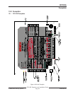
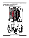
Wiring......................................................23
Command Centers ............................ 23
D8125 POPEX................................... 38
Detection Devices .............................. 23
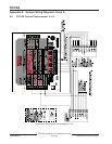
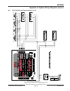
Diagrams .............................. 61, 62, 63
OctoPOPITs ....................................... 43
On-board Points ................................ 35
POPITs ........................................ 23, 38
Z
ZONEX 1
Point Address Charts ......................... 65
ZONEX bus ............................................47