


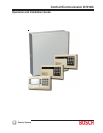

D7212G Operation and Installation Guide
Page 6 © 2003 Bosch Security Systems4998138544C
D7212G
Contents
11.5 SDI Address 88 .................................................................................................................................................................. 54
11.5.1 D9133DC Direct Connect Programming Module ...................................................................................................... 54
11.5.1.1 Connecting the D9133DC ............................................................................................................................................... 54
11.5.1.2 Used as an External Modem ............................................................................................................................................ 54
11.5.2 D9133TTL-E Network Interface Module ....................................................................................................................... 55
11.5.3 Address Settings ................................................................................................................................................................. 55
11.5.4 Supervision ........................................................................................................................................................................... 55
12.0 Programmer and Accessory Connections ...................................................................................... 57
12.1 Programmer Connector .....................................................................................................................................................57
12.1.1 Programmer Access Reports ........................................................................................................................................... 57
12.2 Accessory Connector ........................................................................................................................................................57
13.0 Faceplate........................................................................................................................................................... 59
13.1 D7212G Faceplate............................................................................................................................................................ 59
Appendix A: System Wiring Diagrams, Issue A ........................................................................................... 61
A.1 D7212G Control/Communicator, 1 of 3 .......................................................................................................................61
A.2 D7212G Control/Communicator, 2 of 3 ...................................................................................................................... 62
A.3 D7212G Control/Communicator, 3 of 3 ...................................................................................................................... 63
Appendix B: Point Address Chart ....................................................................................................................... 65
B.1 ZONEX 1, Points 9 to 40 ................................................................................................................................................ 65