


D7212G Operation and Installation Guide
D7212G
Page 57© 2003 Bosch Security Systems 4998138544C
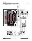
12.0 Programmer and Accessory Connections
12.1 Programmer Connector
The procedure below shows how to connect and disconnect the programmer. Refer to the D5200 Programmer Manual (P/N:
74-06176-000) for complete information on using the D5200 programmer.
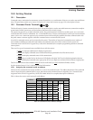
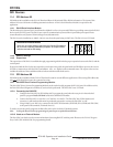
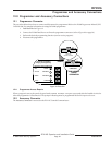
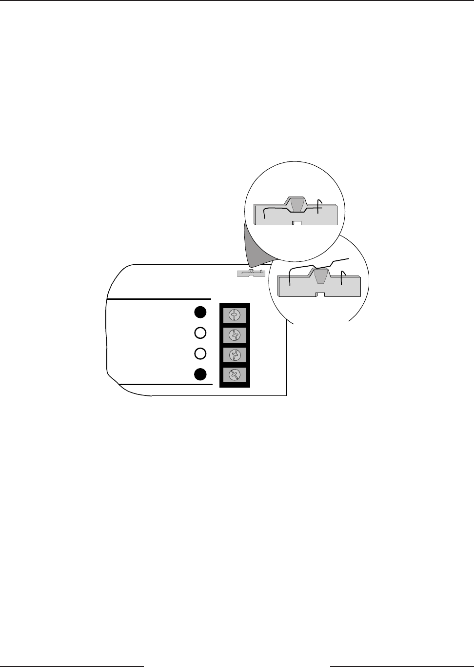
1. Lock Reset Pin: See Figure 19.
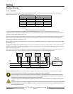
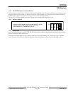
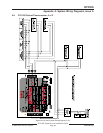
2. Connect the D5200 Data/Power cord into the programmer connector (refer to Figure 20 on page 58).
3. Perform the desired programming function (send or receive program).
4. Disconnect the programmer.
Reset Pin
Disable All Except Battery
Charging And Programming
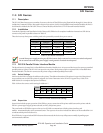
PERIPHERAL DEVICE CONNECTIONS
RED POWER +
YELLOW DATA BUS A
GREEN DATA BUS B
BLACK COMMON
32
31
30
29
RESET PIN
LOCKED (CLOSED)
RESET PIN
NORMAL (OPEN)
FOR NORMAL
PANEL
OPERATION
Figure 19: Reset Pin
12.1.1 Programmer Access Reports
When a program is sent to the panel, the panel sends a PROG ACCESS OK report ten seconds after the handler is exited or
when the programmer is disconnected. The prompt in Routing must be programmed Yes for this report to be sent.
12.2 Accessory Connector
The Accessory Connector is not used on the D7212G Control/Communicator.
Programmer and Accessory Connections