


D7212G Operation and Installation Guide
Page 32 © 2003 Bosch Security Systems4998138544C
D7212G
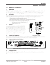
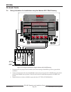
Telephone Connections
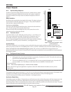
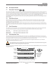
6.6 Operation Monitor LED (Green)
The green Operation Monitor LED indicates the operation of the CPU (Central Processing Unit). When the CPU is operating
normally, the LED flashes 0.5 sec. on, 0.5 sec. off.
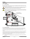
The green LED also serves as a ring indicator. The LED is located on the lower right side (see Figure 9 on page 31). When
there is ring voltage on the phone line (the phone is ringing), the green LED flickers at a faster rate for the duration of each
ring. Ring voltage must reach a minimum of 45 VAC before the system detects it.
6.7 Dialing Format
The system can be programmed to use DTMF or pulse dialing. See Phone Parameters in the D7212G Program Entry Guide
(P/N: 4998138538).
6.8 Phone Line Monitor
The panel has a built-in phone line monitor that tests the phone line for voltage. The normal voltage on a telephone line is
approximately 48 VDC (24 VDC for some phone systems). The phone line monitor senses trouble when the voltage on the
line falls below 3.0 VDC.
If the monitor senses trouble, it starts a programmable phone line trouble timer. The timer continues to run as long as the
monitor senses trouble. It resets to zero when the panel senses a normal line. If the timer reaches the delay time in the Phone
Supervision program item, it begins a phone line trouble response. Programming determines what the response is. See Phone
Parameters in the D7212G Program Entry Guide (P/N: 4998138538).
Anytime the D7212G uses the phone line to make a call(s) or is on-line with RAM IV, it ceases to monitor the phone line
during this process. Once the phone line on the D7212G is no longer in use, it begins once again to monitor the phone line.
Bad line may test OK: The telephone line monitor uses voltage levels to test the status of the phone line. In some instances a
given telephone line may be out of service without affecting the voltage on the line. The phone line monitor can not recognize
this trouble condition.
6.9 Called Party Disconnect
Telephone companies provide “called party disconnect” to allow the called party to terminate a call. The called party must go
on hook (hang up) for a fixed interval before a dial tone is available for a new call. This interval varies with telephone
company equipment. D7212G firmware allows for “called party disconnect” by adding a 35 second “on hook” interval to the
dial tone detect function. If the panel does not detect a dial tone in seven seconds, it puts the phone line on hook for 35
seconds to activate “called party disconnect,” goes off hook and begins a seven-second dial tone detect. If no dial tone is
detected, the panel dials the number anyway. Each time the number is dialed, the panel records this as an attempt.
6.10 Communication Failure
After two attempts to reach the receiver, a COMM FAIL PH # event is generated. This event (COMM FAIL PH #) will
then be sent first, followed by the original event.
After ten attempts to reach the receiver, the panel goes into communication failure. The panel clears any reports in its phone
buffer and COMM FAIL RTE # event is generated, which appears in the display at command centers. A trouble sounder
can be programmed to annunciate at the command centers. An hour after the COMM FAIL RTE # is generated, the panel
attempts to send this event (COMM FAIL RTE #), if programmed. If the COMM FAIL RTE # event is the only event in
the queue and is unable to reach the central station, the command centers will not turn on the trouble sounder again.
6.10.1 Enhanced Communication
The D7212G Control/Communicator has the ability to transmit events over the SDI Bus to a D9133TTL-E Network
Interface Module. For more information on Enhanced Communications capabilities, please refer to RADXAUX1 in the
D7212G Program Entry Guide (P/N: 4998138538).