


D7212G Operation and Installation Guide
Page 50 © 2003 Bosch Security Systems4998138544C
D7212G
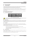
10.2.2 Installation
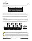
Consult the command center Operation and Installation Guide for installation and mounting instructions. Command
centers connect to the panel in parallel as shown in Table 13.
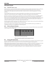
D7212G Command Center
Terminal Function Wire Color Function
32* POWER + Red 12 VDC
31 DATA BUS A Yellow Data-In
30 DATA BUS B Green Data-Out
29 COMMON Black Common
* Connect with at least 5 ft. (1.5 m) of 22 AWG wire (14 ft. [4.3 m] of
18 AWG wire).
Table 13: Command Center Connections
Switching the green and yellow wires affects other command centers: Incorrectly connecting the green wire from the
command center to Terminal 31 and the yellow wire to Terminal 30 causes other command centers connected to the panel to
go blank and/or sound random beep tones.
Devices can be connected to the data bus, Terminals 30 and 31, by parallel wire runs from the panel to each device, wire from
device to device, or a combination of the two as long as a maximum of 15000 ft. (4572 m) of 22 AWG wire for all devices
connected to the SDI Bus combined is used.
It is recommended, however, that command centers be limited to 2000 ft. (610 m) per run and the D9131A be limited to 1000
ft. (305 m) per run.
Extra power needed for more command centers: The D1255 Command Center draws 104 mA when it is idle. It draws 206 mA
with the keys lit and the sounder activated. Review Section 5.0 Power Outputs on page 29 to determine the total power output
requirements for the system.
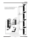
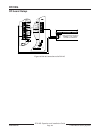
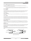
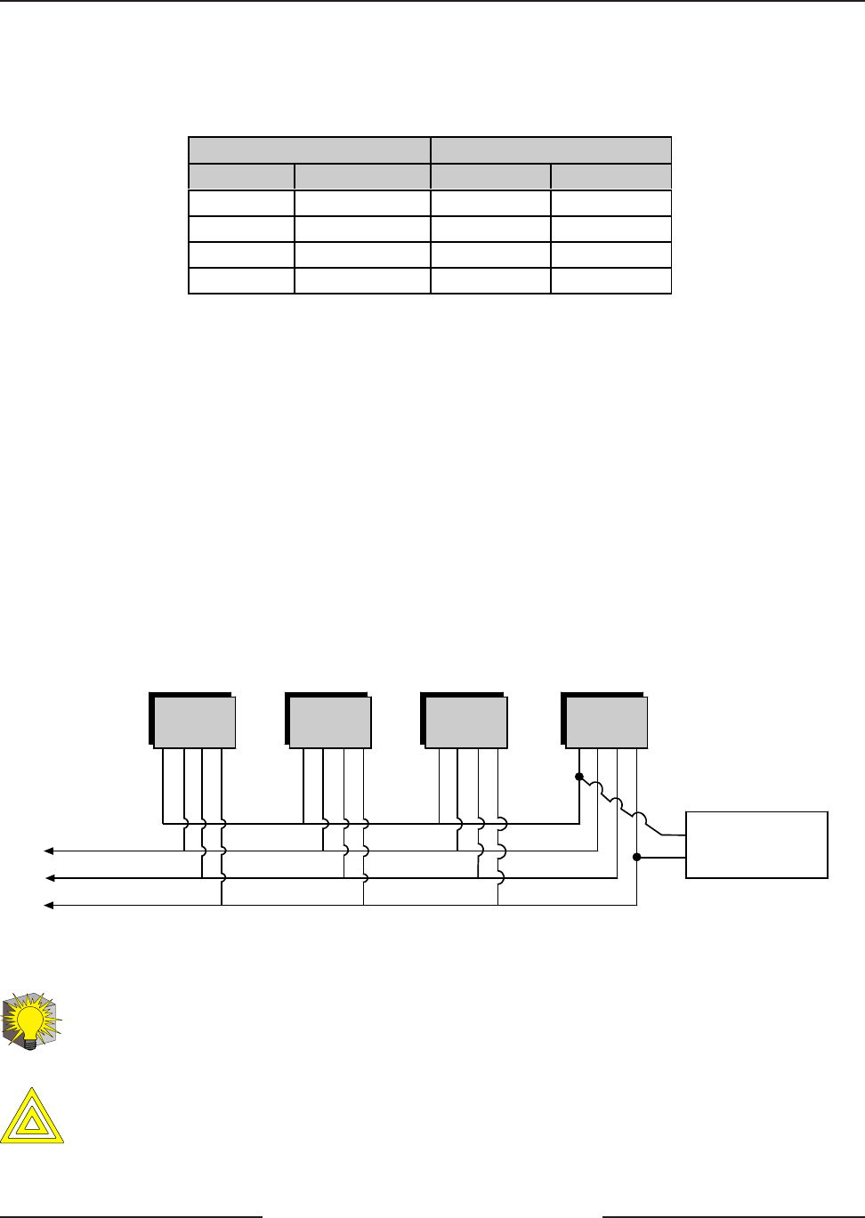
One or more D8132 Battery Charger/Power Supply Modules may need to be added for the number of command centers
that will be used. Figure 17 shows the D8132 powering command centers in a stand-alone configuration.
To
Panel
D8132 or
External
Power Supply
+12 VDC
COMMON
+12 VDC
DATA
DATA
COMMON
Figure 17: Power at Command Centers
For UL certificated accounts, use a UL Listed power supply. The D8132 is not UL Listed as a stand-alone power supply.
Application
Tip
Control/Communicator and D8132 (or other power supply) must share COMMON:
Note that Figure 17 shows the common from the D8132 Module connected to both the command centers' common
and the common on the control/communicator. Any stand-alone power supply powering any device connected to
the panel must also be connected to a common terminal on the panel.
CAUTION
If you are using the Ground Fault Detect capability on the D7212G Control/Communicator and an external power
supply:
Make sure that the external power supply selected isolates its Earth Ground connection from the negative side of the
Aux Power output. External power supplies that do not isolate Earth Ground will cause ground fault conditions on
the control/communicator.
Arming Devices