


D7212G Operation and Installation Guide
D7212G
Page 49© 2003 Bosch Security Systems 4998138544C
10.0 Arming Devices
10.1 Description
Command centers, maintained or momentary contact keyswitches, or a combination of the two are used to arm and disarm
areas. The panel may contain up to 4 areas. See Section 2.4.2 Areas and Accounts on page 17 for a description of areas.
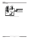
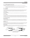
10.2 Command Center Terminals
The Bosch Security Systems command center is a 4-wire powered device used to arm and disarm areas, annunciate complete
system status, initiate system tests, and control many functions of the security system.
The system can supervise up to eight command centers. The panel transmits a serial device trouble report, SDI FAILURE
in the Modem IIIa
2
format or TROUBLE ZN D in the BFSK format, if it loses communication with a supervised command
center. CALL FOR SERVICE appears in any command center with text display capability that loses communication with
the panel. SERVC KEYPAD appears at all other command centers connected to the system.
A total of 32 command centers can be connected to the system. The number of supervised command centers, number of
areas, and the available power affect the total number of command centers that can be connected to the system. See
Command Center in the D7212G Program Entry Guide (P/N: 4998138538) for complete programming details on command
center options.
There are five types of command centers available for use with the system:
•
D1255: 16-character alphanumeric display for general use.
•
D1256: text display command center with functional keys optimized for local fire alarm control.
•
D1257: text display command center for fire annunciation.
•
D1260: Easy-to-read 4-line by 20-character LCD display with eight “Soft” keys for displaying simple selections.
•
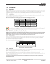
D720: LED display command center appropriate for use as a single area command center with up to eight points.
The D1255 and D720 are also available in
white (D1255W and D720W) or red (D1255R and D720R) versions.
See the command center’s User’s Guide for operational information.
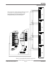
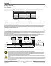
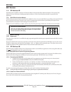
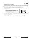
10.2.1 Assigning the command center an address
Switches on the command center assign an address (1 to 8) to the command center. The address determines if the command
center is supervised, the command center's scope, and what area the command center is assigned to. See Command Center
Assignment in the D7212G Program Entry Guide (P/N: 4998138538) for a complete description of addresses.
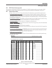
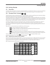
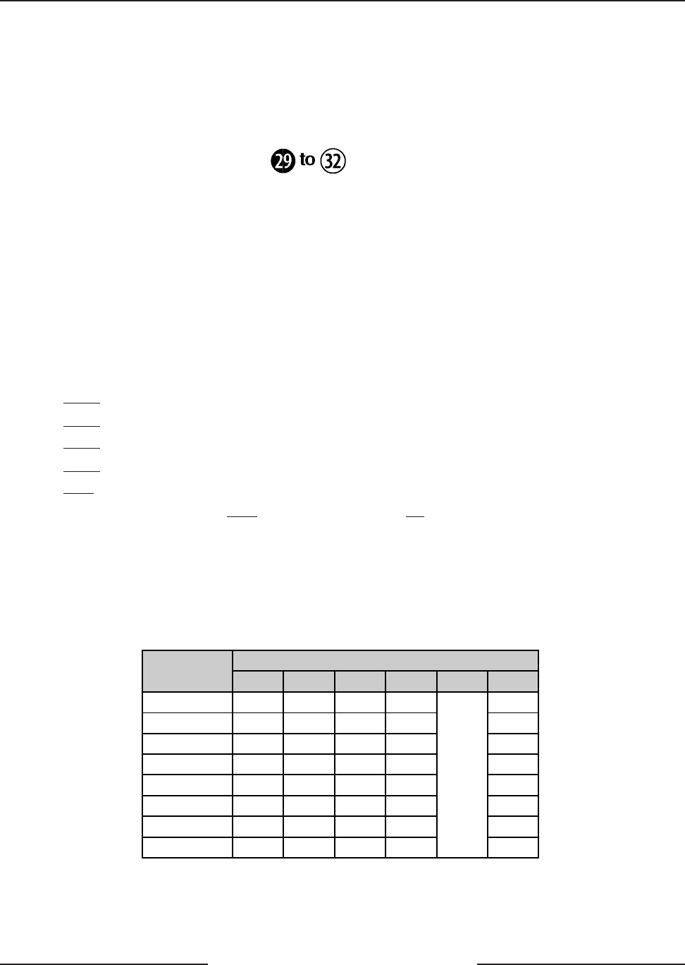
Table 12 shows the correct switch setting for each address.
Switch
Address
1 2 3 4 5 6
Address #1 ON ON ON ON ON
Address #2 OFF ON ON ON ON
Address #3 ON OFF ON ON ON
Address #4 OFF OFF ON ON ON
Address #5 ON ON OFF ON ON
Address #6 OFF ON OFF ON ON
Address #7 ON OFF OFF ON ON
Address #8 OFF OFF OFF ON
Encoding Tone ON/OFF
ON
Table 12: Command Cneter Address Settings
Arming Devices