


D7212G Operation and Installation Guide
D7212G
Page 47© 2003 Bosch Security Systems 4998138544C
Off-board Relays
9.0 Off-board Relays
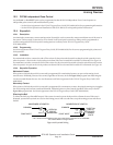
9.1 D8129 OctoRelay
The D8129 OctoRelay allows the addition of relay outputs to the system in groups of eight. The D7212G allows up to 24
OctoRelay outputs to be added to the system. Review Section 5.0 Power Outputs on page 29 to be sure to provide enough
power for the OctoRelays and other powered devices that will be connected to the system.
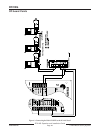
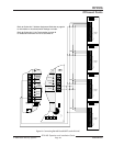
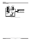
OctoRelays for relay numbers 1 to 24 connect to ZONEX 1, Terminal 28. See Figure 16 on page 48.
Alarm output, auxiliary relay, sensor reset, arming status, point status, alarm memory, or remote functions can be assigned
to the OctoRelay outputs individually. See Relay Parameters in the D7212G Program Entry Guide (P/N: 4998138538) for
programming details.
D8129 restricted for fire systems: The D8129 relay outputs are not supervised and can not be used in fire or combined fire/
burglary installations for primary indicating devices.
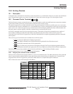
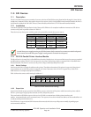
9.1.1 Configuring the D8129 OctoRelay
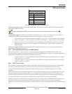
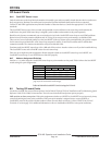
Five switches on the OctoRelay determine the relay numbers for the eight relay outputs. Refer to Table 11.
Panel Relay
Number
D8129 OctoRelay
Switch Setting
D8129 OctoRelay Switch
Setting
1 to 8 Off-On-On-On-On ZONEX 1 Terminal 28
9 to 16 On-Off-On-On-On ZONEX 1 Terminal 28
17 to 24 Off-Off-On-On-On ZONEX 1 Terminal 28
Table 11: D8129 OctoRelay Switch Settings
CAUTION
Relay outputs may activate while you are setting the OctoRelay switches or programming the panel. You may wish
to disconnect equipment connected to relay outputs before performing these functions.
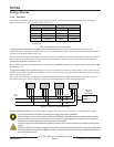
9.1.2 Relay Outputs
Each OctoRelay output provides a Form C dry contact rated for 1.0 A at 12 VDC. Normally-open, common, and normally-
closed terminals are available for each relay output. When an individual output is activated, there is continuity between the
normally-open and common terminals. When the output is not activated, there is continuity between the normally-closed
and common terminals.
9.1.3 Installation
Set the switches on the OctoRelay before installing it in the enclosure. See Section 9.1.1 Configuring the D8129 OctoRelay.
Install the OctoRelay in the enclosure with the panel (see Figure 2 on page 21) or in an adjacent enclosure not more than 5 ft.
(1.5 m) from the panel. Use 16 to 22 AWG wire.
Follow the procedure below to install OctoRelays in the enclosure with the panel.
1. Align the module with one of the mounting locations in the enclosure. See Figure 2 on page 21.
2. Use the screws provided with the module to secure it in the enclosure.
Use the D137 Mounting Bracket or D9002 Mounting Skirt to install OctoRelays in enclosures with no module
mounting locations available.
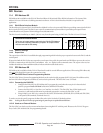
9.1.4 Wiring Connections
Power down the panel to connect OctoRelays as shown in Figure 16 on page 48. Note that OctoRelays for relay numbers 1 to
24 connect to ZONEX 1, Terminal 28.
Only one OctoRelay is shown wired to each ZONEX bus in Figure 16. Wire additional OctoRelays in parallel. Review Section
5.0 Power Outputs on page 29 to be sure to provide enough power for the relays.