


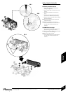
FAULT FINDING
INSTALLATION & SERVICING INSTRUCTIONS FOR WORCESTER GREENSTAR 24 i junior/28 i junior
8 716 107 336b (11/05)
55
FAULT FINDING
& DIAGRAMS
Off
On
Slow flash
(normally off,
flashes on)
Slow flash
(normally on,
flashes off)
Fast flash
Fast flash
2 pulses
5 pulses
Off
Off
Flashing (reset required)
Flashing (reset required)
Off
Flashing
No light
No light
Permanent mains supply to boiler.
Boiler mains switch.
Fuse F1, 2.5A or Fuse F3, 0.5A
Transformer (both coils below 100Ω).
Otherwise replace control board.
Live demand at ST10-L
R (from external roomstat/timer).
Facia mounted timer (if fitted).
CH knob in winter position.
Diverter valve.
Control board.
Some older thermostats (containing capacitors) may give a low
voltage return at ST10-LR when the thermostat contacts are open.
Check that there is not a permanent live at ST10-LR from another
source.
See Flow Sensor Test below.
or
Diverter valve.
Control board.
Fan.
Control board.
Gas present and at correct pressure.
Combustion CO
2
level.
Flue condition.
Ignition electrodes / harness / connections.
Gas valve (coils 140-190Ω) / low voltage harness connection.
Otherwise replace control board.
Heat exchanger blocked.
Heat exchanger baffles removed and not refitted.
Water pressure.
All air vented.
Pump / harness / connections.
Water leaks / blockages.
Safety thermostats / low voltage wiring harness / connections.
Otherwise replace control board.
Blockage in flue system.
Temperature sensor (8000-20,000Ω).
Low voltage wiring harness / connections to sensor.
Fan / fan harness / connections to fan.
Code plug fitted.
Replace control board
Service mode selected to min, press service button to return to normal.
Service mode selected to max, press service button to return to normal.
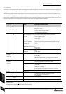
NOTE : This fault finding information is for guidance only. Worcester cannot be held responsible for costs incurred by persons not deemed
to be competent.
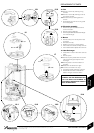
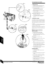
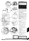
The electronic control system for this boiler incorporates a blue central indicator. This normally confirms the permanent mains supply but, by
flashing at different rates during a fault, provides a guide to the cause as listed.
This fault finding system assumes that the appliance has been operating normally until the time of failure (i.e. not a first installation error).
PRELIMINARY CHECKS : Preliminary electrical system checks are the first electrical checks to be carried out during a fault-finding
procedure. On completion of the Service/Fault-Finding task which has required the breaking and remaking of electrical connections, check
(a) EARTH CONTINUITY, (b) SHORT CIRCUIT CHECK, (c) POLARITY and (d) RESISTANCE TO EARTH.
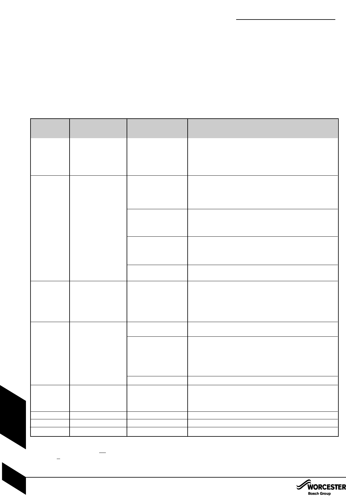
FAULT FINDING
Blue light
indication
Lockout reset
button
Possible solution/check
Fault
No power at control board
Boiler not operating during
central heating demand
(HW ok)
Boiler operating
without live demand at
ST10-LR (from external
roomstat timer).
Boiler not operating during
hot water demand (CH ok).
Boiler not operating during
any demand.
Ignition lockout
Flue overheat
Heat exchanger overheat
Flue blockage
Volatile lockout
Internal fault
Not a fault code
Not a fault code
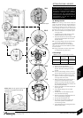
Flow Sensor Test
:Replace control board if: 5V is not across the red and black cables.
:1.5V-3.5V is across the yellow and black cables (with water flowing).
Otherwise replace flow sensor.