


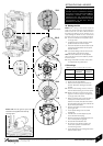
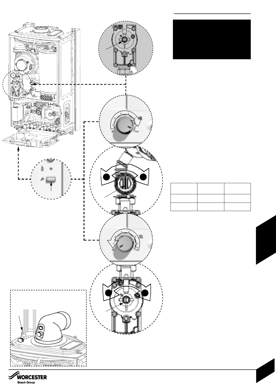
33. Setting the CO
2
Note: When running in the service mode, the
boiler will operate both the central heating &
DHW circuits. This is to allow sufficient time for
the setting procedure. It will be necessary to run
water through the DHW circuit to ensure that
the boiler will not cycle on low heating demands.
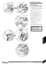
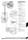
5.1 Connect manometer to inlet pressure point
on the gas valve.
To adjust the CO
2
it will be necessary to first
operate the boiler at maximum output.
Press and hold down the service button (A) for
10 seconds until illuminated. The blue power
indicator will flash.
5.2 Turn central heating control to maximum; the
boiler will then go to maximum output.
Note: The control will resume normal operation
after 15 minutes or if the service button is pressed
for over a second.
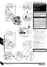
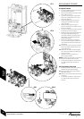
5.3 Using a flat blade screwdriver set the CO
2
via adjuster (B) using table below.
Check CO is less than 200ppm.
Measure the inlet pressure; it should be no
less than 18.5mb for natural gas and 37mb
for LPG.
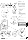
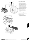
5.4 Set the central heating control to minimum.
This will make the boiler go to minimum power.
5.5 Measure the CO
2
; it should now be at the
figure for minimum output. If not adjust (C)
on the gas valve until correct.
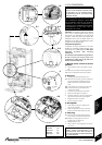
Return to maximum and re-check the CO
2
. If
correct press and hold down the service
button for 2 seconds; the button will cease to
be illuminated and the blue power indicator will
be permanently illuminated.
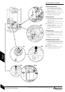
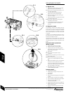
Remove manometer and re-seal inlet pressure
point on gas valve.
Fit new plastic sealing cover on to outlet
adjuster (B).
Fit white cover over valve adjuster (C) and
secure with black security tag.
Remove red arrow from data plate and fit new
one in correct position for gas type.
Re-assemble and refit boiler case.
Re-connect mains electrical supply and
check boiler operation as stated in the
commissioning section.
Fit new label from kit over existing label on the
appliance bottom panel.
33.1
33.3
5.5
33.4
Inlet Test Nipple
+
–
C
B
C
+
–
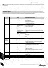
Gas type
CO
2
settings
Note. CO
2
should be measured after 10 minutes
Natural gas
LPG
9.8% ±0.2
11.0%±0.2
9.2% ±0.2
10.5%±0.2
CO
2
setting
maximum
CO
2
setting
minimum
33.2
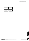
SETTING THE GAS / AIR RATIO
A
THE SETTING OF THE GAS RATIO MUST BE
CARRIED OUT BY A COMPETENT PERSON.
SETTING OF THE GAS RATIO MUST NOT BE
ATTEMPTED UNLESS THE PERSON
CARRYING OUT THE CONVERSION IS
EQUIPPED WITH A COMBUSTION ANALYSER
CONFORMING TO BS 7927 AND IS
COMPETENT IN ITS USE.
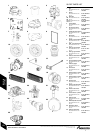
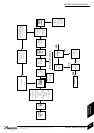
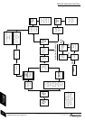
REPLACEMENT OF PARTS
INSTALLATION & SERVICING INSTRUCTIONS FOR WORCESTER GREENSTAR 24 i junior/28 i junior
8 716 107 336b (11/05)
52
SERVICING
& SPARES
Please note: The flue gas test point can be
accessed on the appliance flue elbow by
removing cap D
D