


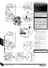
REPLACEMENT OF PARTS
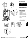
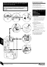
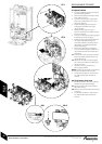
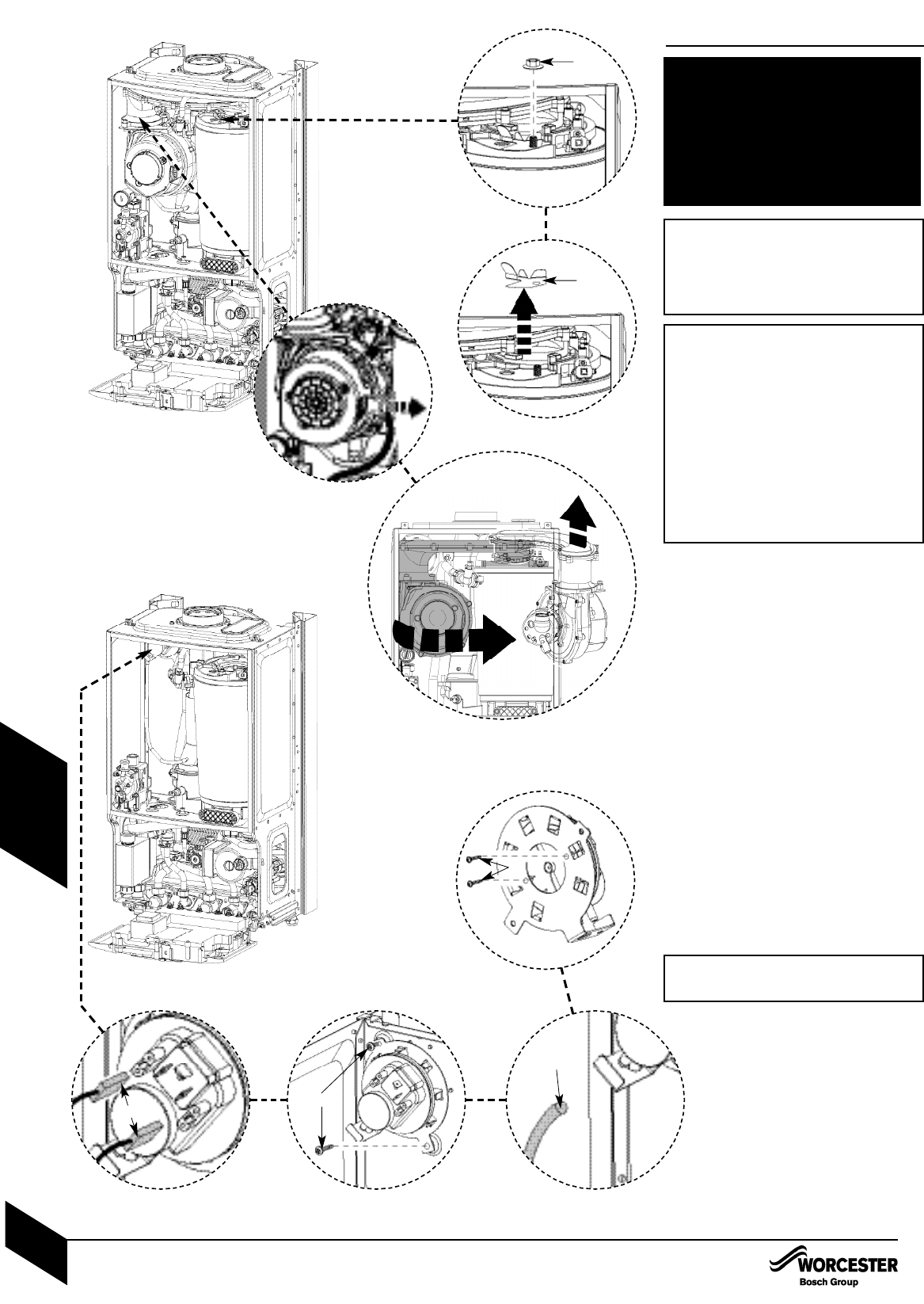
13. Air / gas manifold and fan
assembly
Remove electrical connector from fan.
Remove wire clip from gas valve outlet then
pull gas adjustment assembly free from
plastic connector and pull clear of case
(see 6.1).
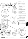
13.1
Undo and remove securing nut (A)from the
top of the heat exchanger.
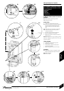
13.2
Remove stainless steel viewing mirror (B).
13.3
Rotate fan and air/gas manifold assembly
(shaded) around the top of the heat
exchanger until the lug on the air/gas
manifold is visible.
Lift up assembly and remove from boiler.
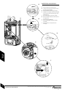
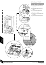
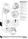
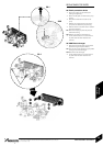
14. Pressure switch
14.1
Remove electrical connections (C).
14.2
Slacken top retaining screw and remove
bottom screw. (D).
14.3
Remove tube (E).
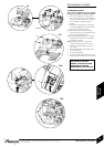
14.4
Remove 2 screws (F)retaining pressure
switch to bracket.
Refit new pressure switch to bracket.
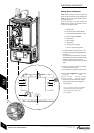
The following components require
the air / gas manifold and fan
assembly to be removed:
Pressure switch
Fan
Electrode assembly
Burner
Heat exchanger
13.1
13.2
14.4
14.314.214.1
A
B
C
D
E
F
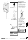
13.3
IMPORTANT: IF THE JOINT
BETWEEN THE AIR/GAS MANIFOLD
AND THE HEAT EXCHANGER IS
DISTURBED THE SEALING GASKET
MUST BE REPLACED.
IMPORTANT: ENSURE TUBE IS
REFITTED TO PRESSURE SWITCH
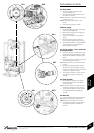
IMPORTANT: AFTER REASSEMBLY
THE COMBUSTION MUST BE
CHECKED USING THE PROCE-
DURE IN THE SECTION “SETTING
THE GAS AIR RATIO”. MEASURE-
MENT AND SETTING (IF NECES-
SARY) OF THE GAS RATIO MUST
NOT BE ATTEMPTED UNLESS THE
PERSON IS EQUIPPED WITH A
COMBUSTION ANALYSER CON-
FORMING TO BS 7927 AND IS COM-
PETENT IN ITS USE.
REPLACEMENT OF PARTS
INSTALLATION & SERVICING INSTRUCTIONS FOR WORCESTER GREENSTAR 24 i junior/28 i junior
8 716 107 336b (11/05)
45
SERVICING
& SPARES