


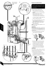
FLUE OPTIONS
INSTALLATION & SERVICING INSTRUCTIONS FOR WORCESTER GREENSTAR 24 i junior/28 i junior
8 716 107 336b (11/05)
17
PRE -
INSTALLATION
FLUE OPTIONS
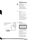
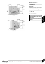
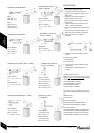
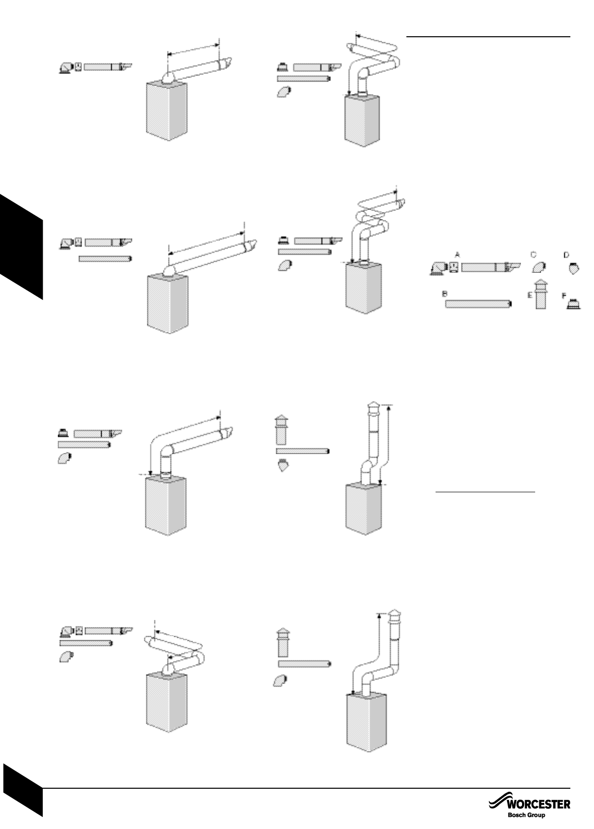
• The diagrams (opposite) show the
components used and the maximum flue
length for each configuration of 100mm and
125mm flues.
• Shaded flue components indicate the
standard 100mm horizontal flue.
• Only straight flue sections can be reduced in
length and cut.
• The flue terminal end can be fitted from the
inside or outside of the building.
• Fixing kits are supplied with the flue extension
kits.
• Horizontal 125mm and Vertical 100mm and
125mm flue kits are available with separate
instructions. Contact your supplier or
Worcester.
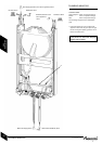
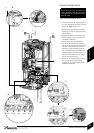
A - Standard horizontal flue (100mm diameter
shown)
B - Straight flue extension
C - Flue bend 90°
D - Flue bend 45°
E - Vertical terminal (vertical adaptor supplied
with terminal)
F - Vertical adaptor (used with horizontal
terminal)
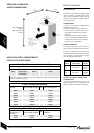
Calculating the flue length:
Measure the total flue length required, noting
that the max
imum straight flue length including
the terminal is:
Horizontal 60/100mm: 4600mm
Horizontal 80/125mm: 13000mm
Vertical 60/100mm: 6400mm
Vertical 80/125mm: 15000mm
Then reduce the total straight flue length for
each extra flue bend (excluding the flue elbow)
by:
2000mm for 90°
1000mm for 45°
Flue Extension lengths:
Horizontal & Vertical 60/100mm: 960mm
Horizontal & Vertical 80/125mm: 1000mm
Flue Terminal lengths:
Horizontal 60/100mm: 800mm including terminal
Horizontal 80/125mm: 1200mm including terminal
Vertical 60/100mm: 1140mm to top of terminal
Vertical 80/125mm: 1365mm to top of terminal
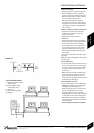
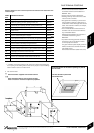
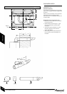
STANDARD FLUE HORIZONTAL
Ø100
MAX 686 A x 1
MIN 250 A x 1*
Ø125
MAX 1070 A x 1
MIN 250 A x 1*
* Requires cutting
MAXIMUM FLUE HORIZONTAL
Ø100 - 4600mm
A x 1 + B x 5
Ø125 - 13000mm
A x 1 + B x 13
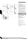
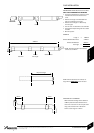
MAXIMUM FLUE VERTICAL START + 1 BEND
Ø100 - 4600mm
A x 1 + C x 1 + B x 5 +
Fx1
Ø125 - 13000mm
A x 1 + C x 1 + B x 13 +
Fx1
Ø100 - 2600mm
A x 1 + B x 3 + C x 1
Ø125 - 11000mm
A x 1 + B x 11 + C x 1
MAXIMUM FLUE HORIZONTAL + 1 BEND
MAXIMUM FLUE VERTICAL
START + 2 BENDS
Ø100 - 2600mm
A x 1 + C x 2 + B x 4 +
Fx1
Ø125 - 11000mm
A x 1 + C x 2 + B x 13 +
Fx1
Ø100 - N/A
Ø125 - 9000mm
A x 1 + C x 3 + B x 11 +
Fx1
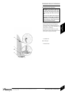
MAXIMUM FLUE VERTICAL
WITH 2 x 45° BENDS
Ø100 - 4400mm
(including terminal)
B x 5 + D x 2 + E x 1
Ø125 - 13000mm
(including terminal)
B x 13 + D X 2 + E x 1
Ø100 - 2400mm
(including terminal)
B x 4 + C x 2 + E x 1
Ø125 - 11000mm
(including terminal)
B x 13 + C x 2 + E x 1
VERTICAL FLUE WITH
2 x 90° BENDS
A
A
B
A
B
F
C
A
B
C
F
B
C
A
F
B
C
A
E
B
D
E
B
C
MAXIMUM FLUE VERTICAL
START + 3 BENDS