


A
E
D
B
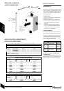
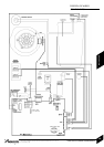
BOILER CONNECTIONS
INSTALLATION & SERVICING INSTRUCTIONS FOR WORCESTER GREENSTAR 24 i junior/28 i junior
8 716 107 336b (11/05)
21
INSTALLATION
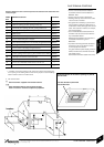
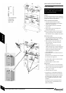
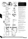
Handling
Hole
Do not lift by the
air gas manifold.
3
C
1A
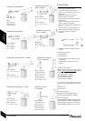
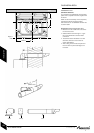
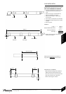
22mm 15mm 22mm 15mm 22mm
2 & 4
H
1
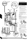
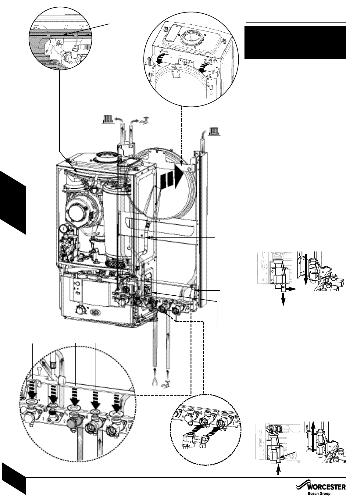
BOILER CONNECTIONS
CAUTION: ISOLATE THE MAINS GAS
SUPPLY BEFORE STARTING ANY WORK
AND OBSERVE ALL RELEVANT SAFETY
PRECAUTIONS.
4
2
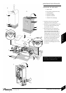
Stop in
locked
position
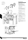
GAS AND WATER CONNECTIONS:
Remove template and secure the wall
mounting frame to the wall with the fixings
supplied.
System pipes may be run vertically upwards
behind the boiler or below it. See
Plumbing Manifold Section on page 15.
A - CH flow (22mm), B - CH return (22mm),
C - Gas inlet (22mm), D - Mains water inlet
(15mm), E - DHW outlet (15mm)
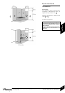
1. If using the optional filling loop 7 716 192
281 (not supplied with the boiler) fit it
before hanging the boiler on the wall frame.
1A. Fit sealing washers to service valves
before hanging boiler.
NOTE: The bonded washer supplied is for the
Gas connection only.
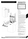
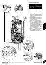
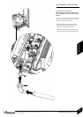
IMPORTANT:
Before hanging the boiler onto the wall
mounting frame ensure that the pressure relief
valve connection is in the DOWN position. This
is located on the right hand side of the wall
frame at the rear.
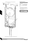
2. Pull the extended tab/lever forward and
down until there is no further travel.
3. Hang the boiler on to the wall mounting
frame by the two brackets positioned left
and right at the top rear of the appliance.
Do not lift the appliance by the air gas
manifold. There are two handling holes
incorporated into the inner casing left and
right in the lower section of the appliance.
IMPORTANT:
The pressure relief connector must be
repositioned after the boiler has been correctly
mounted to the wall mounting frame.
4. Push the lever on the pressure relief
connector UP until the stop on the inside of
the handle is over the shoulder of the metal
bracket to secure in place.