


7
Form 6104 BCF14N-R0299
Instruction Manual – Model CF1400 Oil Burner
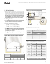
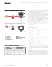
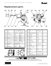
Figure 5 - Nozzle line assembly in burner
Z
1408
a
Measure dimension from
front (flat) face of head to
end of air tube, as shown.
Z
b
c
d
Measure dimension Z from the flat
surface between (not on) the raised fins.
1424
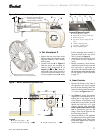
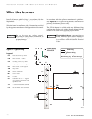
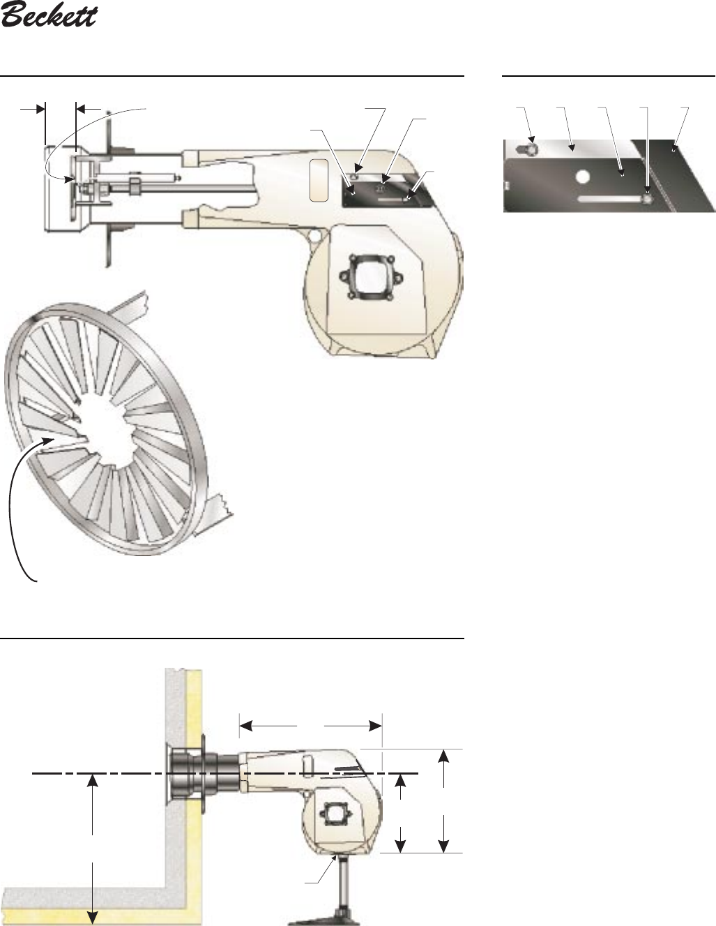
Figure 7 - Burner installed in appliance front
1403
D
H
K
J
a
b
c
Legend
H Housing total length — 18"
J Center to bottom of housing — 10
⁷⁄₈⁷⁄₈
⁷⁄₈⁷⁄₈
⁷⁄₈" K Overall housing height — 13
³⁄₈³⁄₈
³⁄₈³⁄₈
³⁄₈"
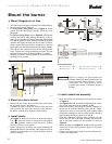
❏ Set dimension Z
• Replace the rear access door on the
burner, making sure that the adjust-
ing plate assembly is now securely
held in place.
• Loosen acorn nut d in Figure 5.
Slide the nozzle line and plate as-
sembly until dimension Z in
Figure 5 is
1³⁄₄1³⁄₄
1³⁄₄1³⁄₄
1³⁄₄" ±
¹⁄₁₆¹⁄₁₆
¹⁄₁₆¹⁄₁₆
¹⁄₁₆". When di-
mension Z (from end of air tube to
flat area of front face of head) is cor-
rectly set, tighten acorn nut d. Verify
that the adjusting plate assembly is
properly seated at the rear access
door, as shown in Figure 5.
• Attach the oil line from the oil valve
to the nozzle line end. Tighten se-
curely.
• Before proceeding, check dimen-
sion Z once again. Loosen acorn nut
d if necessary to reposition the
nozzle line. Once dimension Z is set,
do not loosen acorn nut d again.
For the setting of acorn nut c, refer
to page 12.
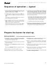
Figure 6 - Adjusting plate assy.
1408-1
e f
g
cd
Legend (Figures 5 and 6)
a Adjusting plate assembly
b Spline nut for securing nozzle line
c Bottom acorn nut
d Top acorn nut (for setting dim. Z
only)
e Indicator adjusting plate
f Secondary adjusting plate
g Primary adjusting plate
❏ Insert burner
• Position the burner in the front of
the appliance and loosely tighten
the nuts on the mounting studs. The
burner should be pitched downward
2° as shown in Figures 3 and 7.
• See Figure 7. Install the pedestal
support kit (recommended) by at-
taching the ¾" npt flange (item a)
to the bottom of the burner using
the (4) #10 screws provided. Cut and
thread (one end only) a ¾" pipe
nipple (item b) with length 11
inches less than dimension D in Fig-
ure 7
. Thread the pipe into the
flange. Then slip the pipe end into
the floor flange (item c).
• Secure the burner to the appliance
by tightening the nuts on the burner
flange mounting studs. Then secure
the pedestal support floor flange set
screw to the pipe.