


11
Form 6104 BCF14N-R0299
Instruction Manual – Model CF1400 Oil Burner
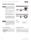
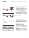
Sequence of operation — typical
1. On call for heat from the appliance operating controls (and
the circuit from T to T of the R8184 closed), power is
applied to the R8184 black wire (BK).
2. The R8184 applies 120 volts to the orange wire (OR), acti-
vating the burner motor (M1) and the ignition transformer
(TR).
The oil pump is operated by the burner motor, so oil pres-
sure is delivered to the oil valve inlet.
3. Power is applied to the oil valve circuit. If optional timer,
(TM), is installed, oil flow will be delayed for the timer
duration, thus providing a prepurge period.
When the timer times out, the oil valve(s) (S1, and S2 if
supplied
) is activated, allowing oil to flow to the nozzle.
4. At the start of the cycle, the R8184 begins checking for
flame signal between F and F. Flame must be established
within 15 seconds of initiation. If no flame is sensed after
15 seconds, the R8184 will terminate all power to the
blower and oil circuits, shutting the burner down. The con-
trol will electrically lock out.
• To reset the control after lockout, wait 2 to 3 minutes
after lockout to give the internal switch time to cool.
Then push the reset button on the primary control, al-
lowing the burner to operate in normal sequence.
• Troubleshoot the reason for flame sense failure.
5. When the call for heat signal terminates (at the black wire
of the R8184), the R8184 terminates power to all circuits,
closing the oil valve and stopping the burner motor.
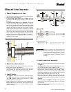
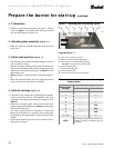
Prepare the burner for start-up
Start-up checklist – Verify the following before attempting to start burner.
❏ Combustion air supply and venting have been inspected
and verified to be free of obstructions and installed in
accordance with all applicable codes.
❏ Oil nozzle has been selected correctly and securely installed
in the nozzle adapter.
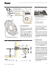
❏ Fuel unit by-pass plug has not been installed for one-pipe
oil system.
By-pass plug has been installed for two-pipe oil system.
❏ Fuel connection to nozzle line assembly is secure.
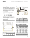
❏ Dimension Z has been set per this instruction manual.
❏ Fuel supply line is correctly installed, the oil tank is
sufficiently filled, and shut-off valves are open.
❏ Burner is securely mounted in appliance, with pressure
firing plate and gasket installed for pressurized chamber
application.
❏ Appliance has been filled with water (boilers) and controls
have been operationally checked.
❏ Burner has been installed in accordance with appliance
manufacturer’s instructions (when available).
❏ Also refer to appliance manufacturer’s instructions (when
available) for start-up procedures.