


12
Form 6104 BCF14N-R0299
Instruction Manual – Model CF1400 Oil Burner
Prepare the burner for start-up - continued
❏ Z dimension
• Should be set per these instructions (see page 7). The top
acorn nut (Figure 11, item d) should never be loosened
once the Z dimension is initially set.
❏ Adjusting plate assembly (Figure 11)
• Make sure spline nut (item b) and bottom acorn nut (item
c) are loose.
❏ Initial head position (Figure 11)
• The indicator plate assembly (item e) markings correspond
to head position settings.
• Slide the secondary adjusting plate (item f) toward the rear
of the burner until the number on the indicator plate corre-
sponds to the initial head setting given in Table 4 for the
desired firing rate.
• Figure 11 shows a typical example, with a head setting of
5.
• When the head position has been set, tighten the bottom
acorn nut (item c) and the spline nut (item b).
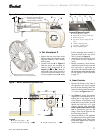
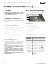
❏ Initial air settings (Figure 12)
• Loosen the screw holding the air adjusting plate (item m).
Set the air to the desired rate. (The numbers on this plate
correspond to the approximate firing rate settings given in
Table 5.)
• Rotate the air adjusting plate until the lower edge of the
pointer is opposite the number from Table 5 corresponding
to the desired firing rate.
• This initial setting should be adequate for starting the
burner. Once the burner is in operation, the air setting will
be adjusted for best performance as discussed later in this
manual.
• Follow the procedures given later in this manual for fine-
tuning the air settings.
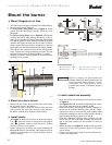
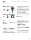
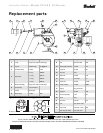
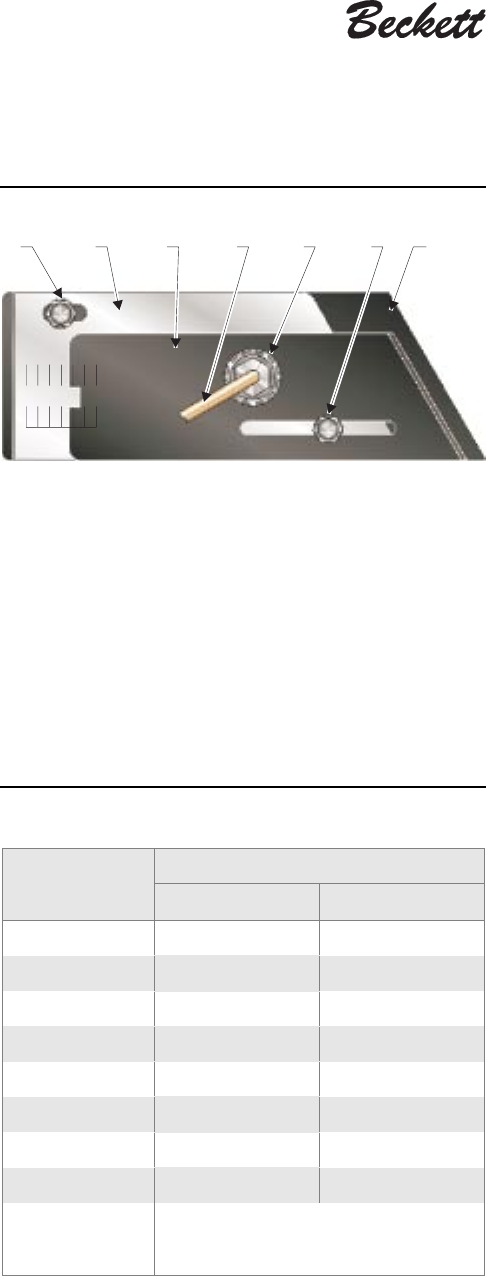
Figure 11 – Adjusting plate initial setting, typical
1407
934
5
678
e
g
cd f
bh
Legend (Figure 11)
b Spline nut for securing nozzle line
c Bottom acorn nut (for head adjustments)
d Top acorn nut (for setting dimension Z only
— do not loosen after setting dimension Z)
e Indicator adjusting plate
f Secondary adjusting plate
g Primary adjusting plate
h Copper oil line from oil valve to nozzle line
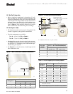
Table 4 – Initial indicator adjustment plate settings
(head position)
Approximate
adjusting plate
settings
Firing rate, gph
Tube “A” Tube “B”
0 — —
1 — —
2 4.00 —
3 6.00 —
4 7.00 7.00
5 8.00 8.00
6 10.00 10.00
7 – 12 — —
NOTE
These settings are approximate, and can very
depending on actual job conditions and over-
fire pressure.