


13
Form 6104 BCF14N-R0299
Instruction Manual – Model CF1400 Oil Burner
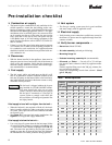
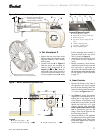
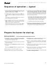
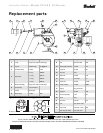
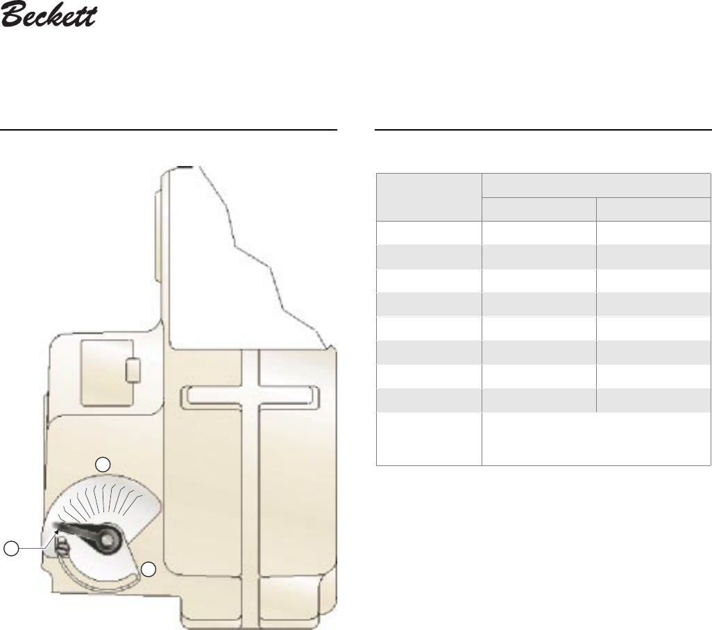
Figure 12 – Air damper assembly Table 5 – Initial air adjusting plate settings
(damper position)
12
0
1
2
3
4
5
6
7
8
9
10
11
1409o-2
h
k
m
Legend (Figure 12)
h Damper label - position indicator for air adjusting plate
k Damper indicator - permanently attached to damper
m Air adjusting plate - sets air position
Approximate
head settings
Firing rate, gph
Tube “A” Tube “B”
0 4.00 4.00
1 4.50 7.50
2 5.00 8.00
3 6.00 9.00
4 7.00 10.00
5 7.50 —
6 8.00 —
7 – 10 — —
NOTE
These settings are approximate, and can
vary depending on actual job conditions
and overfire pressure.
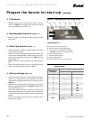
❏ Set appliance limit controls
• Set the appliance limit controls in accordance with the
appliance manufacturer's recommendations.
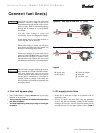
❏ Prepare the fuel unit for air venting
• To vent air from one-pipe oil systems, attach a clear hose to
the vent plug on the fuel unit. Provide a container to catch
the oil. Loosen the vent plug.
• Vent the air as described under Start the burner, page 14.