


10
Form 6104 BCF14N-R0299
Instruction Manual – Model CF1400 Oil Burner
Wire the burner
Install the burner and all wiring in accordance with the
National Electrical Code and all applicable local codes or
requirements.
Wire the burner in compliance with all instructions provided
by the appliance manufacturer. Verify operation of all controls
in accordance with the appliance manufacturer's guidelines.
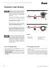
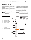
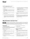
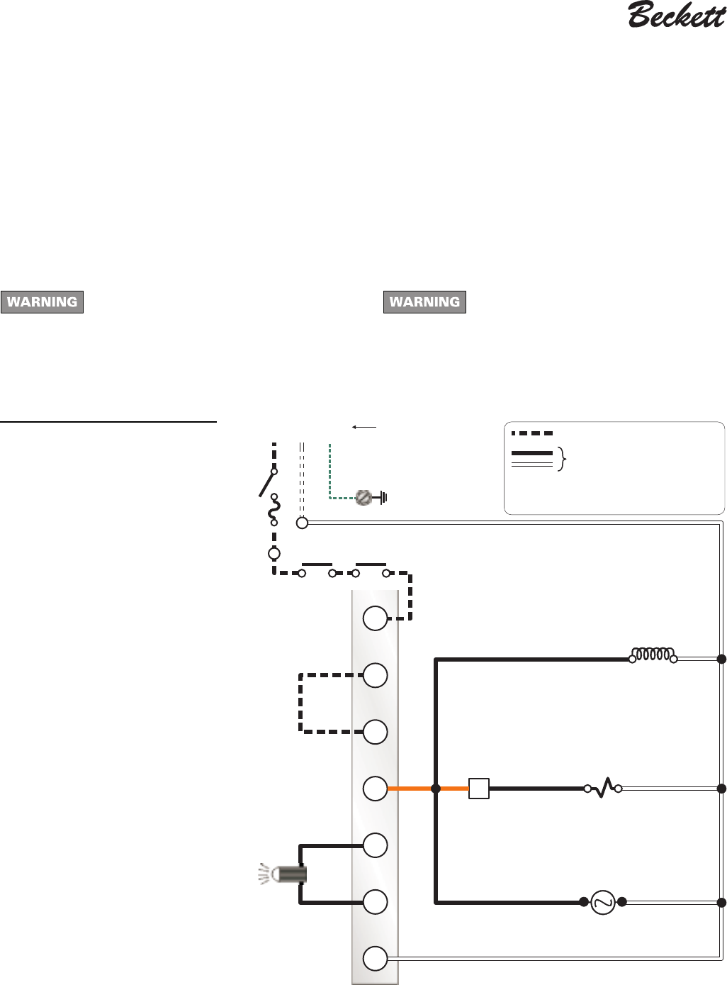
See Figure 10 for a typical wiring diagram, with R8184 oil
primary, for reference purposes only.
The CF1400 burner is available with many different wiring
configurations. Refer to the wiring diagram shipped with the
burner for the actual wiring applying to your burner.
Do not by-pass any safety control.
By-passing a safety control could result in
severe personal injury, death or substantial
property damage.
Electrical shock hazard - can cause injury or
death. Disconnect power before installing or
servicing. Provide ground wiring to the burner
in accordance with the National Electrical
Code.
Legend
FD Fused disconnect, by others
LM Limit controls, by others
OP Operating controls, by others
PR Oil primary control, R8184 typical
CC Flame sensor, cad cell typical
TM Delay timer
TR Ignition transformer
M1 Burner motor
S1 Oil valve
S2 Redundant oil valve — supplied
only if burner is equipped with
type H fuel unit.
T-T 24-volt thermostat/limit terminals
F-F Cad cell flame sensor terminals
Figure 10 – Typical wiring
BK
T
T
OR
F
F
WH
HNG
T
OR OR
WH
WH
WH
WH
BK
BK
TR
TM
FD
PR
Power supply
120v/60 hz
S1
CC
M1
LM OP
BK = black
OR = orange
WH = white
Motor M1 wiring 14 ga All other wiring 16 ga
1411o
Field wiring
Factory wiring