


5
Form 6104 BCF14N-R0299
Instruction Manual – Model CF1400 Oil Burner
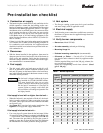
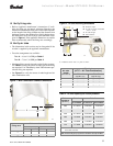
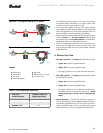
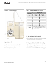
Figure 1 - Min. Combustion chamber dimensions
1405
A
L
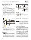
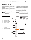
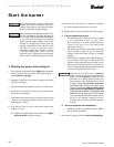
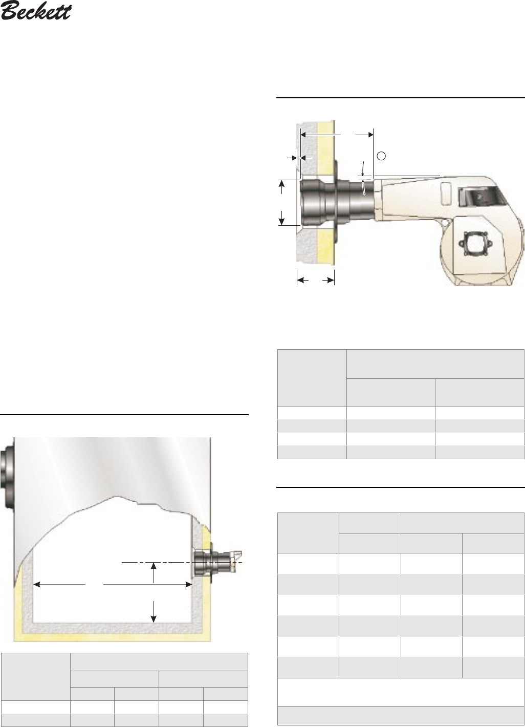
Figure 2 - Air tube mounting dimensions
E
T
D
2°
1404
G
1
E Insertion depth
G Air tube to inside of chamber
– 0.25" ± 0.125"
T Air tube length
D Tube diameter
① Install the burner with a 2° pitch as shown.
Air tube
length
(Dimension T)
A.T.C. Codes
(A.T.C. = Air Tube Combination)
Tube A
(Dim. D = 5½")
Tube B
(Dim. D = 5¾")
6.75"
CF 66 KD CF 66 KE
10.25"
CF 102 KD CF 102 KE
13.75"
CF 136 KD CF 136 KE
17.75"
CF 176 KD CF 176 KE
Table 2 - Air tube capacity vs. firebox pressure
Firebox
pressure
(In. w.c.)
Tube A Tube B
10% turndown No reserve air 10% turndown
0.0 11.0 GPH 13.6 GPH 12.2 GPH
0.2 10.5 GPH 13.1 GPH 11.7 GPH
0.4 10.1 GPH 12.5 GPH 11.2 GPH
0.6 9.6 GPH 12.0 GPH 10.8 GPH
0.8 9.2 GPH 11.4 GPH 10.3 GPH
1.0 8.7 GPH 10.9 GPH 9.8 GPH
Note: 10% turndown indicates sufficient reserve air to reduce the CO
2
in the
flue to 90% of its value.
Note:
The above ratings may vary 5% due to variations in actual job conditions.
❏ Verify firing rate
• Refer to appliance manufacturer’s instructions (if avail-
able) for firing rate and nozzle selection. Otherwise, the
maximum recommended firing rate for the burner depends
on the length of the firing chamber and the distance from
the burner center to the chamber floor. Verify that the cham-
ber dimensions are at least as large as the minimum values
given in Figure 1. If the appliance dimensions are smaller
than recommended, reduce the firing rate accordingly.
❏ Verify air tube
• The information in this section may be disregarded if the
air tube is supplied by the appliance manufacturer.
• Two tube arrangements are available –
Tube A — 4.0 to 11.0 GPH per Table 2
Tube B — 7.0 to 13.6 GPH per Table 2
• Maximum firing capacity depends on the firebox pressure.
Use Table 2 to verify the correct air tube type for the firing
rate required. Use Tube B only when Tube A cannot pro-
vide the firing rate required.
• See Figure 2 to verify the correct air tube length and air
tube combination code.
Firing rate
Minimum dimensions
(refractory-lined) (wet-base boilers)
A L A L
0 to 5 gph 7.0" 25.0" 7.0" 25.0"
5 to 10 gph 8.0" 35.0" 8.0" 40.0"