


6104 BCF5 R07 9
125-200 psig
125-200 psig
3502
The burner is shipped without the by-pass plug in-
stalled.
Intall the by-pass plug in two-pipe oil supply systems
ONLY.
y
y
Failure to comply could cause immediate pump
seal failure, pressurized oil leakage and the po-
tential for a fi re and injury hazard.
Do Not Install By-pass
Plug with 1-Pipe System
Install the oil tank and oil lines in accordance with all
applicable state and local codes.
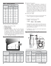
Size the oil supply and return lines using the guidelines
given in the fuel unit literature included in the literature
envelope. Oil line fl ow rate will equal the burner rate for
one-pipe systems. For two-pipe systems, refer to Table
2 for the fuel unit gear set capacity - the rate at which
fuel is recirculated when connected to a two-pipe system.
However, size two-pipe oil lines based on this fl ow rate.
Use continuous lengths of heavy-wall copper tubing,
routed under the fl oor where possible. Do not attach fuel
lines to the appliance or to fl oor joists if possible. This will
reduce vibration and noise transmission problems.
Install an oil fi lter sized to handle the fuel unit gearset fl ow
capacity (Table 2) for two-pipe systems. Size the fi lter
y
y
y
y
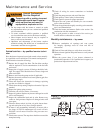
Carefully install the oil supply lines, fi ttings and com-
ponents using the guidelines provided in this section.
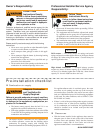
The oil supply must comply with the latest edition
of NFPA 31 (Canada CSA B139) and all applicable
codes.
Do NOT install valves in return lines.
If the oil supply inlet pressure to the pump exceeds 3
psig or for gravity feed systems, install an oil safety or
pressure reducing valve (Webster OSV, Suntec PRV or
equivalent).
y
y
y
y
Failure to properly install the oil
supply system could cause oil
leakage, equipment malfunction,
puff-back of hot gases, heavy smoke,
asphyxiation, explosion and fi re
hazards.
Install Oil Supply To
Specifi cations
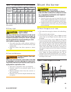
Fuel unit by-pass plug
The CF500 and CF800 burners are shipped without the
by-pass plug installed in the fuel line.
The by-pass plug must NOT be installed when using with
a one-pipe oil system.
The by-pass plug MUST be installed when using a two-
pipe oil system.
Oil supply/return lines
y
y
y
for the fi ring rate for one-pipe systems. Locate the fi lter
immediately adjacent to the burner fuel unit.
Install two high-quality shut-off valves in accessible
locations on the oil supply line. Locate one valve close
to the tank. Locate the other valve close to the burner,
upstream of the fuel fi lter.
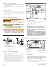
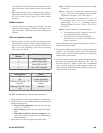
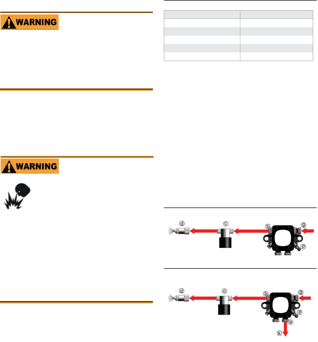
Burner fuel fl ow
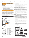
One-pipe systems – See Figure 8 for the fuel fl ow path.
Figure 7 is based on type B fuel unit.
Oil supply connects to one of the fuel unit inlet ports.
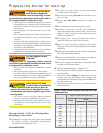
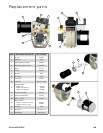
Two-pipe systems – See Figure 9 for the fuel fl ow paths
for two-pipe oil systems.
Figure 9 is based on type B fuel unit .
Oil supply connects to one of the fuel unit inlet ports.
Oil return connects to the fuel unit return port. (Install
the by-pass plug in the fuel unit for two-pipe sys-
tems.)
y
y
y
y
y
y
y
Figure 8 - One-pipe oil fl ow with “B” pump
Figure 9 - Two-pipe oil fl ow with “B” pump
125-200 psig
125-200 psig
3503
Legend
a Return port
b Nozzle port
c Oil valve
d Nozzle & adapter
g Inlet port
k Return line to oil tank
p Air bleed valve
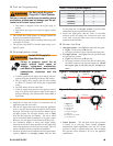
Table 3. Fuel Unit gearset capacity
Fuel unit model number Gearset capacity (GPH)
A2VA-7116
17
A2YA-7916
20
B2VA-8216
21
B2YA-8916
25
B2TA-8248
21
Nozzle pressure – The fuel unit nozzle port pressure
is factory set at 140 psig. Some original equipment
manufacturer burner applications may call for a lower
pressure to obtain a required fi ring rate. Do not change
this pressure unless directed to do so by the appliance
manufacturer.
y