


6104 BCF5 R07 11
Keep Service Access
Covers Securely Installed
These covers must be securely in place to
prevent electrical shock, damage from exter-
nal elements, and protect against injury from
moving parts.
All covers or service access plates must be in place at
all times except during maintenance and service.
This applies to all controls, panels, enclosures, switch-
es, and guards or any component with a cover as part
of its design.
y
y
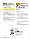
Safety controls are designed and installed to provide
protection.
Do not tamper with, or bypass any safety control.
If a safety control is not functioning properly, shut off
all main electrical power and fuel supply to the burner
and call a qualifi ed service agency immediately.
y
y
y
Tampering with, or bypassing safety controls
could lead to equipment malfunction and result
in asphyxiation, explosion or fi re.
Do Not Bypass Safety
Controls
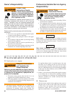
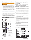
Prepare the burner for start-up
This burner must be installed and prepared for start-up
by a qualifi ed service technician who is trained and ex-
perienced in commercial oil burner system installation
and operation.
Do not attempt to start the burner unless you are fully
qualifi ed.
Do not continue with this procedure until all items in
the “Prepare the burner for start-up” section have been
verifi ed.
Carefully follow the wiring diagrams, control instruc-
tion sheets, fl ame safeguard sequence of operation, test
procedures and all appliance manufacturer’s directions
that pertain to this installation.
If any of these items are not clear or are unavailable,
call Beckett at 1-800-645-2876 for assistance.
y
y
y
y
y
Incorrect installation and mishandling of start-
up could lead to equipment malfunction and re-
sult in asphyxiation, explosion or fi re.
Professional Installation
and Service Required
Oil nozzle has been selected correctly and securely
installed in the nozzle adapter.
Fuel unit by-pass plug has not been installed for one-
pipe oil system.
By-pass plug has been installed for two-pipe oil
system.
Fuel connection to nozzle line assembly is secure.
Dimension Z has been set per the ‘Set Z Dimension’
instructions detailed earlier in this manual. The acorn nut
(Figure 7, item C) should never be loosened once the Z
dimension is initially set.
Fuel supply line is correctly installed, the oil tank is
suffi ciently fi lled, and shut-off valves are open.
Burner is securely mounted in appliance, with pressure
fi ring plate and gasket installed for pressurized chamber
application.
Appliance has been fi lled with water (boilers) and controls
have been operationally checked.
Burner has been installed in accordance with appliance
manufacturer’s instructions (when available).
Also refer to appliance manufacturer’s instructions (when
available) for start-up procedures.
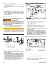
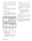
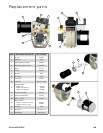
Initial head position (Figure 7)
The indicator plate assembly markings correspond to head
position settings.
Loosen the fastener (Figure 7, item d) and slide the
indicator plate until the number on the indicator plate
corresponds to the initial head setting listed in Table 4, for
the desired fi ring rate.
When the head position has been set, tighten the fastener
and the spline nut.
y
y
y
Start-up checklist - Verify the following before
attempting to start burner.
Combustion air supply and venting have been inspected
and verifi ed to be free of obstructions and installed in
accordance with all applicable codes.
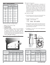
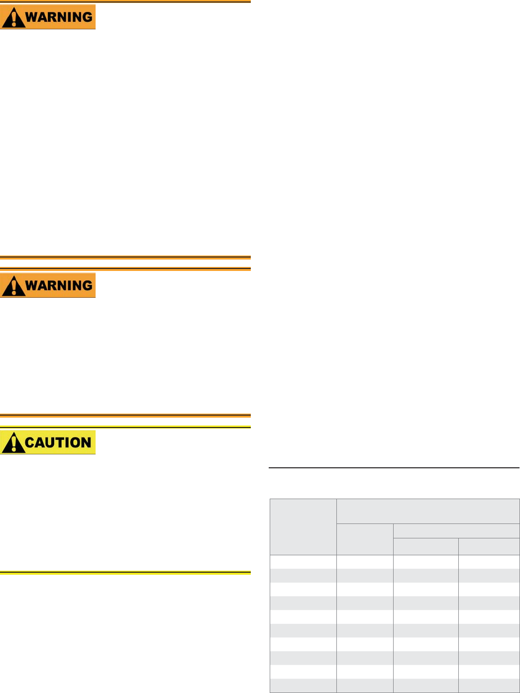
Table 4 - Initial indicator adjustment plate settings
(head position)
Rate GPH
Approximate head settings
CF500
CF800
Tube A Tube B
1.75 0 -- --
2.25 0
3.00 4 0 --
3.50 5 1 --
4.00 5 2 --
5.00 6 4 3
5.50 6 4 4
6.00 -- 4 4
7.00 -- 6 5
8.00 -- -- 6