


6 6104 BCF5 R07
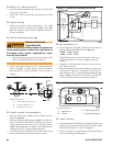
Verify burner components —
Burner, Model CF500 or CF800
Air tube assembly
Mounting fl ange kit
Oil nozzle, per Table 1 — Only 45° to 70° solid pattern
nozzles are recommended unless otherwise specifi ed
by appliance manufacturer. (See specifi c appliance
recommendation sheet or refer to OEM Spec Guide). Find
the required fi ring rate in the 140 psig column (factory-set
fuel unit pressure). Select the corresponding nozzle from
column 1 (Rated gph @ 100 psig).
y
y
y
y
Table 1 - Nozzle Capacities
Rated gph @
100 psig
Pressure - Pounds per
square inch
140 150
1.75 2.07 2.14
2.00 2.37 2.45
2.25 2.66 2.74
2.50 2.96 3.06
2.75 3.24 3.37
3.00 3.55 3.68
3.50 4.13 4.29
4.00 4.70 4.90
4.50 5.30 5.51
5.00 5.90 6.13
5.50 6.50 6.74
6.00 7.10 7.33
6.50 7.65 7.96
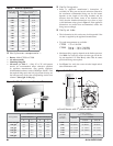
Firing Rate
Minimum Dimensions
(with damper) (without damper)
ALAL
1.75 to 3.00 gph
7.5” 18.0” 8.0” 19.0”
4.00 gph
8.0” 21.0” 9.5” 23.0”
5.00 gph
9.0” 23.0” 10.5” 30.0”
6.00 gph
10.0” 28.0” 11.5” 40.0”
7.00 gph
11.0” 34.0” 12.0” 46.0”
8.00 gph
14.0” 38.0” 14.0” 51.0”
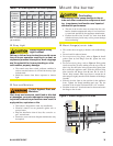
Air Tube
Length
(Dimension T)
A.T.C. Codes
(A.T.C. = Air Tube Combination)
CF500
CF800
Tube A Tube B
6.00” CF 60 KK CF 60 KH CF 60 KJ
8.00” CF 80 KK CF 80 KH CF 80 KJ
10.00” CF 100 KK CF 100 KH CF 100 KJ
14.00” CF 140 KK CF 140 KH CF 140 KJ
16.00” CF160 KK -- --
17.00” -- CF 170 KH CF 170 KJ
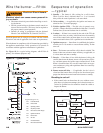
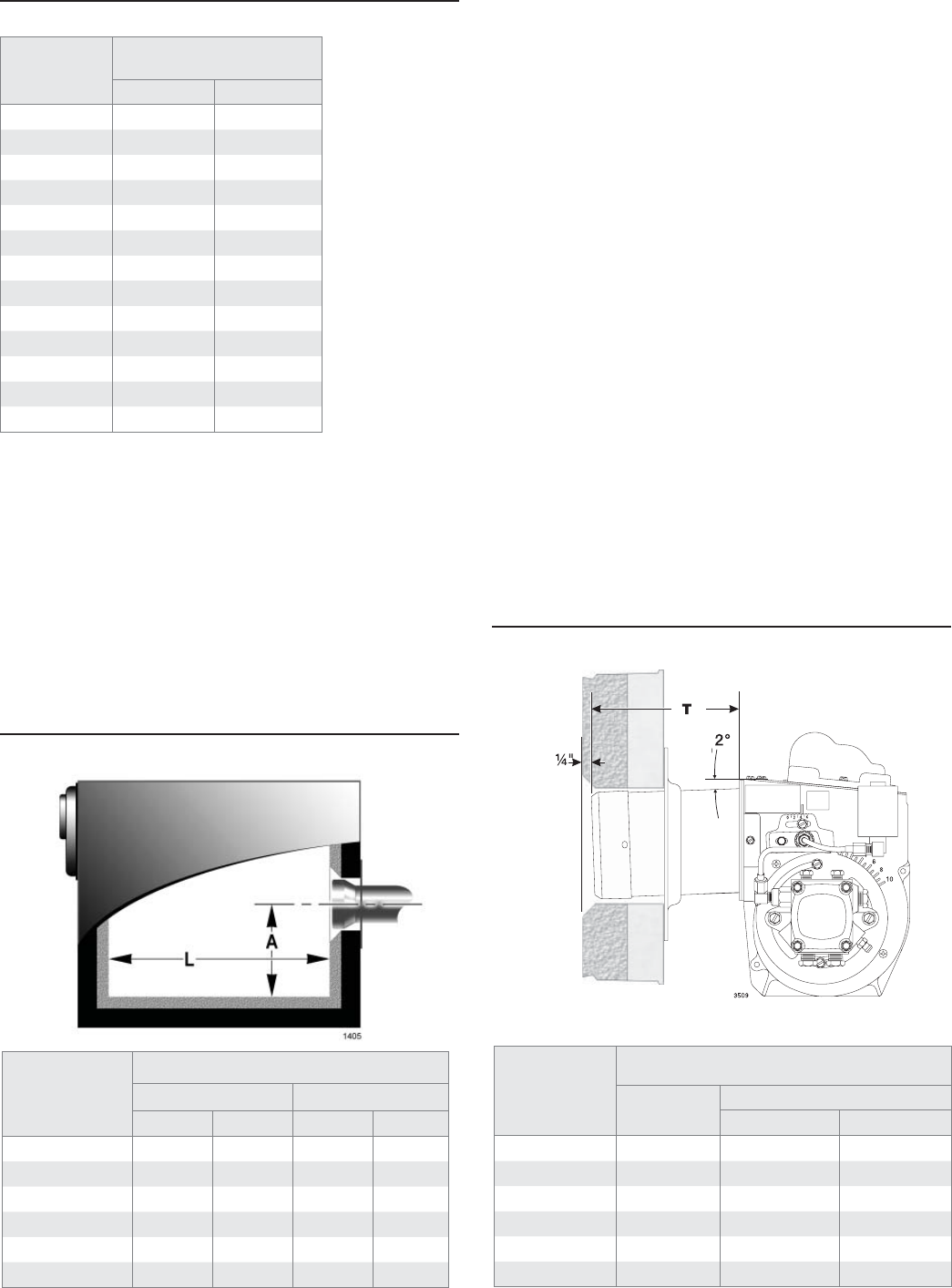
u Install burner with 2
o
pitch as shown.
u
Figure 3 - Air Tube Mounting Dimensions
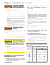
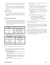
Verify fi ring rate
Refer to appliance manufacturer’s instructions (if
available) for fi ring rate and nozzle selection. Otherwise,
the maximum recommended fi ring rate for the burner
depends on the length of the fi ring chamber and the
distance from the burner center to the chamber fl oor.
Verify that the chamber dimensions are at least as large
as the minimum values given in Figure 2. If the appliance
dimensions are smaller than recommended, reduce the
fi ring rate accordingly.
Verify air tube
The information in this section may be disregarded if the
air tube is supplied by the appliance manufacturer.
Two tube arrangements are available –
CF500 1.75 to 5.50 GPH
CF800 Tube A — 3.00 to 7.00 GPH
Tube B — 5.00 to 8.00 GPH
Maximum fi ring capacity depends on the fi rebox pressure.
Use Table 2 to verify the correct air tube type for the fi r-
ing rate required. Use Tube B only when Tube A cannot
provide the fi ring rate required.
See Figure 3 to verify the correct air tube length and air
tube combination code.
y
y
y
y
y
Figure 2.
Min. Combustion Chamber Dimensions