


6104 BCF5 R07 5
Fuel supply
The fuel supply piping and tank must provide #1 or #2 fuel
oil at pressure or vacuum conditions suitable for the fuel
unit (oil pump) on the burner. Refer to fuel unit literature
in the literature envelope in the burner carton to verify
allowable suction pressure.
If fuel supply is level with or higher than fuel unit —
When the fuel unit is not required to lift the oil, the
installation is usually suitable for either a one-pipe or two-
pipe oil system. The oil pressure at the inlet of the fuel unit
must not exceed 3 psig.
Refer to the Mount the Burner Section of this manual for
one-pipe or two-pipe fuel supply installation instructions.
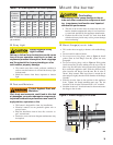
If fuel supply is below the fuel unit —
Use a two-pipe oil system when the fuel unit must lift the
oil more than 8 feet if burner is equipped with a B fuel
unit. The return line provided by the two-pipe system is
needed to purge the air from the fuel lines and minimize
the likelihood of air-related problems during operation.
y
y
y
y
Oil Supply Pressure
Control Required
Damage to the pump, fi lter or other compo-
nent seals could cause possible oil leakage
and potential fi re hazard.
The oil supply inlet pressure to the fuel unit cannot
exceed 3 psig.
Do NOT install valves in return line.
Ensure that a pressure-limiting device is installed in
accordance with the latest edition of the NFPA 31.
y
y
y
Nozzle pressure
The fuel unit nozzle port pressure is factory set at 140
psig. Some original equipment manufacturer burner appli-
cations may call for a lower pressure to obtain a required
fi ring rate. Do not change this pressure unless directed to
do so by the appliance manufacturer.
Electrical supply
Verify that the power connections available are correct for
the burner. Refer to Figure 1. All power must be supplied
through fused disconnect switches.
Vent system
The fl ue gas venting system must be in good condition and
must comply with all applicable codes.
y
y
y
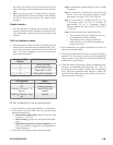
Use only nozzles having the brand, fl ow rate (gph),
spray angle and pattern specifi ed by the appliance
manufacturer.
Follow the appliance manufacturer’s specifi cations for
the required pump outlet pressure for the nozzle, since
this affects the fl ow rate.
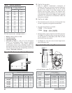
Nozzle manufacturers calibrate nozzle fl ow rates at
100 psig.
This burner utilizes pressures higher than 100 psig, so
the actual nozzle fl ow rate will be greater than the gph
stamped on the nozzle body. (Example: A 4.00 gph
nozzle at 140 psig = 4.70 gph.
For typical nozzle fl ow rates at various pressures
see accompanying chart.
y
y
y
Incorrect nozzles and fl ow rates could
result in impaired combustion, under-
fi ring, over-fi ring, sooting, puff-back
of hot gases, smoke and potential fi re
or asphyxiation hazards.
Correct Nozzle and Flow
Rate Required
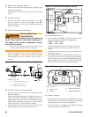
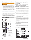
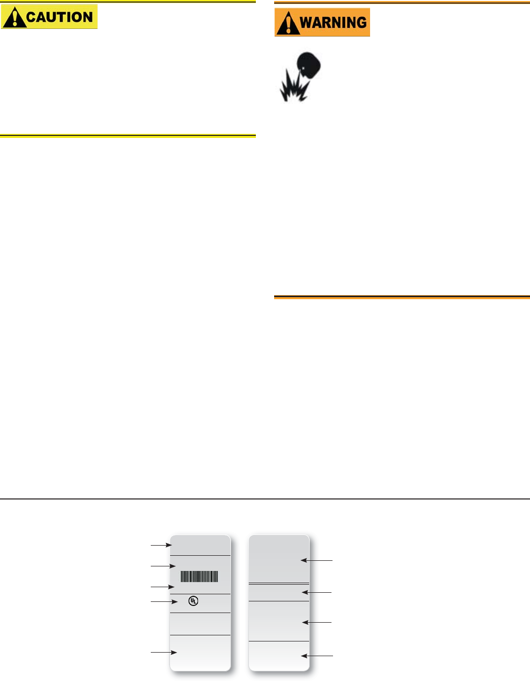
LISTED
(FUEL) BURNER
SERIAL NUMBER
050214-00000
Control Circ: 120V/60Hz 4.5A
Motor Circ: 120V/60Hz 4.0A
Model “XX”
Series (Fuel) Burner
R.W. Beckett Corp.
Elyria, Ohio
Made in the U.S.A.
For use with Group 8 . . .
MP 1192 XX000 R00
X
X
X
X
X
X
XX000 R00
050214-00000
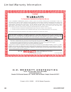
MFR’S SETTINGS
R.W. Beckett Construction & Setting Data
R.W. Beckett Specifi cation
Number and Revision
Boiler Manufacturer and
Model, When Applicable
Additional Codes
General Model Information
Serial Number,Including Date Code
Rating Information
Approval Agency Symbols
Primary Group and Fuel
L0002
Figure 1. Typical Nameplate