


10 6104 BCF5 R07
Wire the burner — R7184
Disconnect electrical power before installing or servic-
ing the burner.
Provide ground wiring to the burner, metal control en-
closures and accessories. (This may also be required to
aid proper control system operation)
Perform all wiring in compliance with the National
Electric Code ANSI/NFPA 70 (Canada CSA C22.1).
y
y
y
Electrical shock can cause severe personal in-
jury or death.
Electrical Shock Hazard
Install the burner and all wiring in accordance with the National
Electrical Code and all applicable local codes or requirements.
Wire the burner in compliance with all instructions provided by
the appliance manufacturer. Verify operation of all controls in
accordance with the appliance manufacturer’s guidelines.
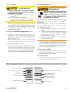
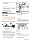
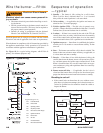
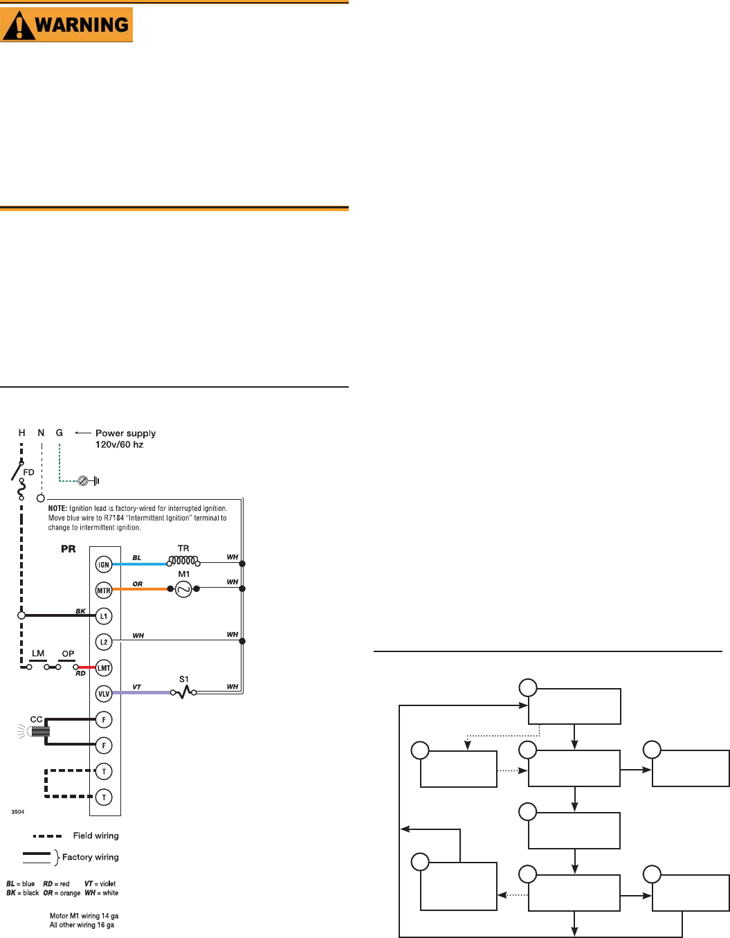
See Figure 10 for a typical wiring diagram, with R7184 oil
primary, for reference purposes only.
Figure 10. - Typical wiring
Legend (Figure 10)
FD
Fused disconnect
LM
Limit controls
OP
Operating controls
PP
Oil primary controls
CC
Flame sensor, CAD cell type
TR
Ignition transformer
M1
Burner motor
S1
Oil valve
T-T
24-volt thermostat
F-F
Flame sensor terminals
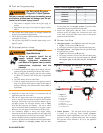
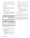
Sequence of operation
— typical
Standby -- The burner is idle, waiting for a call for heat.
When a call for heat is initiated, there is a 3- to 10-second
delay while the control performs a safe start check.
Valve-on delay — As applicable, the ignition and motor are
turned on for a 15-second prepurge.
Trial for ignition (TFI) — The fuel valve is opened, as ap-
plicable. A fl ame should be established within the 15-second
lockout time (30-second lockout time is available).
Lockout — If fl ame is not sensed by the end of the TFI, the
control shuts down on safety lockout and must be manually
reset. If the control locks out three times in a row, the control
enters restricted lockout. Call a qualifi ed service technician.
Ignition carryover — Once fl ame is established, the ignition
remains on for 10 seconds to ensure fl ame stability. It then
turns off.
Run — The burner runs until the call for heat is satisfi ed. The
burner is then sent to burner motor-off delay, as applicable, or
it is shut down and sent to standby.
Recycle — If the fl ame is lost while the burner is fi ring, the
control shuts down the burner, enters a 60-second recycle de-
lay, and then repeats the ignition steps outlined above. If the
fl ame is lost three times in a row, the control locks out to pre-
vent continuous cycling with repetitious fl ame loss caused by
poor combustion.
Burner motor-off delay — If applicable, the fuel valve is
closed and the burner motor is kept on for the selected post-
purge time before the control returns the burner to standby.
Resetting to cad cell
If the control locks out three times in a row without a com-
plete heat cycle between attempts, the lockout becomes re-
stricted. A qualifi ed service technician should be called to
inspect the burner.
1.
2.
3.
4.
5.
6.
7.
8.
y
Figure 11. - Typical sequence of operation
2
1
3
5
6
8
4
7
Standby
Motor-off
delay
(postpurge)
Valve-on
delay
Trial for
ignition
Ignition
carryover
Run
Lockout
Recycle