


6104 BCF5 R07 13
the control will lock out. Press the reset button to reset the
control and return to the functions listed in the previous
step.
Repeat the previous steps if needed, until the pump is
fully primed and the oil is free of bubbles. Then terminate
the call for heat, and the control will resume normal
operation.
Disable function
Any time the motor is running, press and hold the reset
button to disable the burner. The burner will remain off as
long as the button is held and will return to standby when
released.
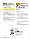
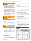
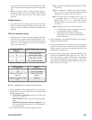
CAD cell resistance check
While the burner is fi ring, and after the ignition has been
turned off, press and release the reset button (hold 1/2 sec-
ond or less) to check the cad cell resistance. The LED will
fl ash 1 to 4 times, depending on the cad cell resistance
(refer to the table below).
Number of LED
fl ashes
Cad Cell Resistance (ohms)
1 Strong (0 to 400)
2 Normal (400 to 800)
3 Weak (800 to 1600)
4 Poor (1600 or higher)*
* Lockout is likely to occur.
LED Indicator Status
On Flame sensed
Off Flame not sensed
Flashing (1/2 sec off - 1/2
sec on)
Lockout/Restricted
Lockout
Flashing (2 sec off - 2 sec
on)
Recycle
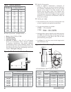
Set combustion using instruments
Allow the burner to run for approximately 5 to 10 minutes.
Set the stack or over-fi re draft to the level specifi ed by the
appliance manufacturer.
Natural Draft Applications; typically over-fi re draft
is -0.01” or -0.02” w.c.
Direct Venting; typically may not require draft adjust-
ment.
High Effi ciency/Positive Pressure Appliances; also
vary from traditional appliances (see manufacturer’s
recommendations).
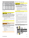
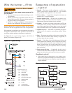
Follow these four steps to properly adjust the burner:
y
y
y
1.
2.
y
y
y
3.
Step 1: Adjust the air shutter/band until a trace of smoke
is achieved.
Step 2: At the trace of smoke level, measure the CO
2
(or O
2
) . This is the vital reference point for further
adjustments. Example: 13.5% CO
2
(2.6% O
2
)
Step 3: Increase the air to reduce the CO
2
by 1.5 to
2 percentage points. (O
2
will be increased by
approximately 2.0 to 2.7 percentage points.)
Example: Reduce CO
2
from 13.5% to 11.5% (2.6%
to 5.3% O
2
).
Step 4: Recheck smoke level. It should be Zero.
This procedure provides a margin of reserve air
to accommodate variable conditions.
If the draft level has changed, recheck the
smoke and CO
2
(or O
2
) levels and readjust the
burner, if necessary
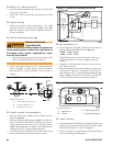
Once combustion is set, tighten all fasteners on air band, air
shutter and escutcheon plate.
Start and stop the burner several times to ensure satisfactory
operation. Test the primary control and all other appliance
safety controls to verify that they function according to the
manufacturer’s specifi cations.
Check the breech draft pressure against the appliance man-
ufacturer’s recommended setting (typically + 0.1” W.C.). If
the breech pressure is higher or lower than recommended
level, adjust the appliance breech damper to achieve the
specifi ed setting. Recheck the smoke and CO
2
(or O
2
) levels.
Adjust burner air if necessary.
y
y
4.
5.
6.