


8 6104 BCF5 R07
50001
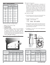
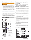
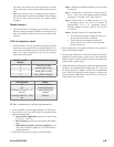
End view Side view
3/16” - 7/32”
gap
1/4” in front
of nozzle
3/16” above
nozzle center
R
P
Q
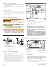
Install nozzle line assembly
Insert the nozzle line assembly into the burner air tube.
Reference Figure 6.
Slide the secondary adjusting plate (Figure 7, item f) com-
pletely to the left on the indicator adjusting plate (item e).
Finger tighten acorn nut (item c) to secure the two plates
together. Slide both plates completely to the right (Indica-
tor Plate will read 0). Tighten fastener (item d).
Install the spline nut on the end of the nozzle line, leaving
the nut loosely placed so the plates can be moved.
y
y
y
Mount air tube to burner
Insert the air tube into the burner housing. Carefully align
the the four screw holes.
Attach the air tube to the burner using the four provided
screws.
Install nozzle
Install the oil nozzle in the nozzle adapter. Use a 3/4”
open-end wrench to steady the nozzle adapter and a 5/8”
open-end wrench to turn the nozzle. Tighten securely but
do not over-tighten.
Check electrode settings
y
y
y
Adjust the electrode gap and position in relation to the
nozzle to the specifi cations shown in Figure 4.
y
Failure to properly maintain these specifi cations
could cause ignition malfunction, puff-back of
hot gases, heavy smoke, asphyxiation, explo-
sion and fi re hazards.
Maintain Electrode
Specifi cations
Check, and adjust if necessary, the critical dimensions
shown in Figure 5. Verify that the oil tube assembly
and electrodes are in good condition, with no cracks or
damage.
y
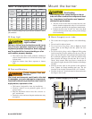
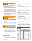
Figure 5 - Nozzle and nozzle line assembly
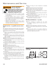
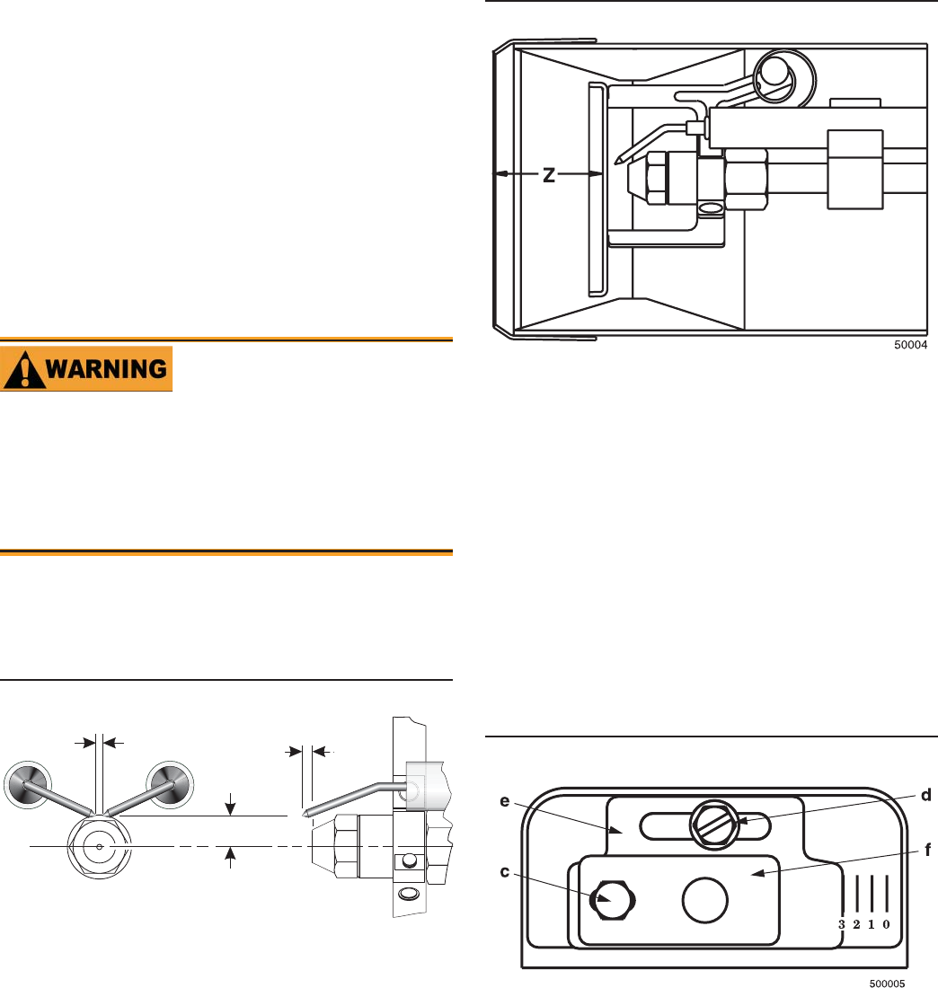
Set dimension Z
Loosen fastener c in Figure 7. Slide the nozzle line and
plate assembly until dimension Z in Figure 6 is:
CF500 - 1-9/16” ±1/16”
CF800 - 1-3/4” ±1/16”.
When dimension Z (from end of air tube to fl at area of
front face of head) is correctly set, tighten acorn nut
(item c).
Attach the oil line from the oil valve to the nozzle line
end. Tighten securely.
Before proceeding, check dimension Z once again. Loos-
en acorn nut c if necessary to reposition the nozzle line.
Once dimension Z is set, do not loosen the acorn nut
(item) c again. Note that for the setting of fastener d,
refer to Initial Head Position procedure on Page 11.
y
y
y
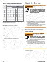
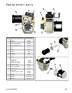
Figure 7 - Adjusting plate assy.
Legend (Figures 7)
c
Bottom acorn nut
d
Fastener
e
Indicator adjusting plate
f
Secondary adjusting plate
Figure 6 - Nozzle line assembly in burner
Insert burner
Position the burner in the front of the appliance and loosely
tighten the nuts on the mounting studs. The burner should
be pitched downward 2° as shown in Figure 4.
Secure the burner to the appliance by tightening the nuts
on the burner fl ange mounting studs.
y
y
CF500
1-9/16”
CF800
1-3/4”
Legend (Figure 5)
P
Nozzle centerline to electrode tip = 1/4”
Q
Nozzle face to electrode tip = 1/8”
R
Electrode spacing = 5/32” gap