


Page 6
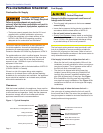
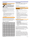
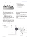
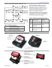
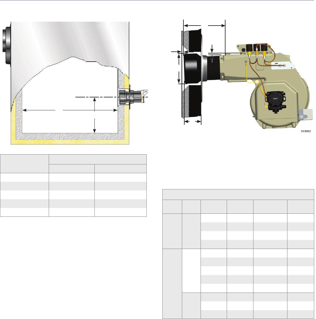
Figure 3 – Air Tube Mounting Dimensions
Legend
D Air Tube Diameter
E Minimum insertion depth
G Air tube to inside of chamber: 1/4” ± 1/8”
T Air Tube Length
Air Tube Combination Codes
Model Tube
Dimension
T
Dimension
D
Code
Dimension
E
CF2500A/
CF2500
KP
6-3/4” 6-1/2” CF 66 KP 3-1/4”
10-1/4” 6-1/2” CF 102 KP 3-1/4”
13-3/4” 6-1/2” CF 136 KP 3-1/4”
17-3/4” 6-1/2” CF 176 KP 3-1/4”
CF3500
KM
8” 8” CF 80 KM 4-1/2”
9-1/4” 8” CF 92 KM 4-1/2”
11-1/2” 8” CF 114 KM 4-1/2”
15” 8” CF 150 KM 4-1/2”
19” 8” CF 190 KM 4-1/2”
KR
11-1/2” 9-15/16” CF 114 KR 5-1/8”
14” 9-15/16” CF 140 KR 5-1/8”
19” 9-15/16” CF 190 KR 5-1/8”
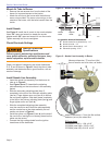
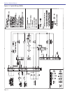
1)
Install the burner with a 2
o
pitch as shown.
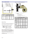
Firing Rate
(gph)
Minimum Dimensions
AL
17 10.5” 48.0”
22 11.5” 58.0”
27 12.5” 66.0”
32 12.5” 73.0”
35 13.0” 77.0”
Figure 2 – Chamber Dimensions
2305
A
L
T
G
E
D
2
o
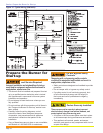
1)
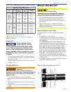
Verify Air Tube
The information in this section may be disregarded if the
air tube is supplied by the appliance manufacturer.
The following tube arrangements are available –
CF2500 - Tube KP -17.0.0 to 19.9 GPH
CF2500A - Tube KP -17.0 to 25.0 GPH
CF3500A - Tube KM -17.0 to 35.0 GPH or
Tube KR -17.0 to 35.0 GPH
Maximum fi ring capacity depends on the fi rebox
pressure. Use Table 2 to verify the correct air tube type
for the fi ring rate required. (Tube KR [CF3500A] is an
optional air tube combination for maximum capacity rate.
It requires a larger I.D. fl ange Number 51631.)
See Figure 3 to verify the correct air tube length and air
tube combination code.
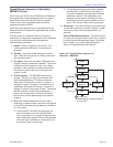
○
○
○
Section: Pre-installation Checklist