


6104 BCF35 R11 Page 17
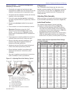
Table 6. Initial Indicator Adjustment Plate Settings
for Head & Damper
Tube
Head Position Damper Position
Approximate
Head Setting
Firing Rate
(gph)
Approximate
Air Damper
Setting
Firing Rate
(gph)
KP (CF2500A / CF2500)
0--0--
1 -- 10 8.00
2 -- 20 9.00
3 17.00 30 11.00
4 17.50 40 12.00
5 18.00 50 15.00
6 18.50 60 17.00
7 19.00 70 18.00
8 20.00 80 19.00
9 21.00 90 20.00
10 25.00 100 22.00
-- -- 105 25.00
KM / KR (CF3500A)
0--00--
1 17.00 10 8.00
2 17.50 20 9.00
3 18.00 30 11.00
4 18.50 40 12.00
5 19.00 50 15.00
6 20.00 60 17.00
7 21.00 70 19.00
8 28.00 80 22.00
9 32.00 90 25.00
10 35.00 100 29.00
-- -- 105 35.00
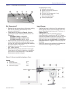
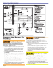
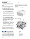
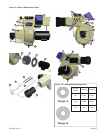
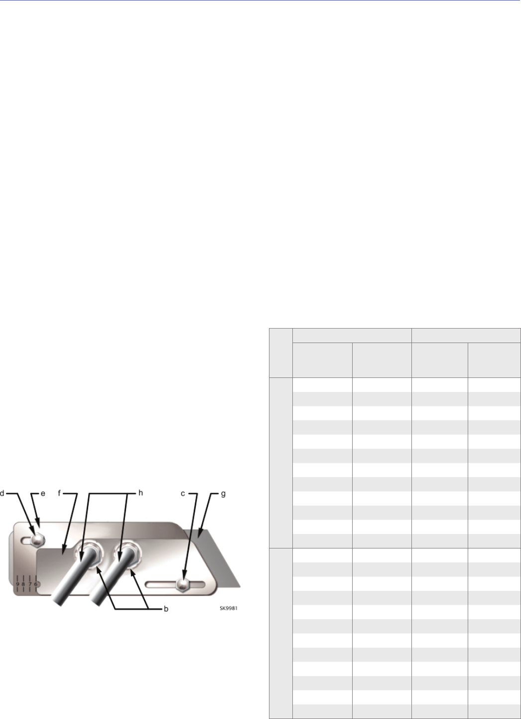
Figure 16 – Adjusting Plate Initial Setting, Typical
Legend
b
Spline nut for securing nozzle line
c
Bottom acorn nut (for head adjustments)
d
Top acorn nut (for setting dim. Z only - do not
loosen after setting Z)
e
Indicator adjusting plate
f
Secondary adjusting plate
g
Primary adjusting plate
h
Copper oil line from oil valve to nozzle line
Z Dimension
The Z Dimension should be set per the instructions
detailed under the heading ‘Set Z Dimension’ previously
in this manual. The top acorn nut (Figure 16, item d)
should never be loosened once the Z dimension has
initially been set.
Adjusting Plate Assembly
Make sure spline nut (item b) and bottom acorn nut (item
c) are loose before proceeding to next section (Figure 16).
Initial Head Position
The indicator plate assembly (item e) markings
correspond to head position settings (Figure 16).
Slide the secondary adjusting plate (item f) toward the
rear of the burner until the number on the indicator plate
corresponds to the initial head setting given in Table 6 for
the desired fi ring rate and burner (high-fi re).
Figure 16 shows a typical example, with a 6 head setting.
When the head position has been set, tighten the
bottom acorn nut (item c) and the spline nut (item b).
○
○
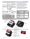
Start-up Checklist – Verify the following before
attempting to start burner.
Combustion air supply and venting have been
inspected and verifi ed to be free of obstructions and
installed in accordance with all applicable codes.
Oil nozzle has been selected correctly and securely
installed in the nozzle adapter.
Fuel unit by-pass plug has not been installed for
one-pipe oil system without a by-pass loop. Refer to
Figure 9.
By-pass plug has been installed for two-pipe oil
system.
Fuel connection to nozzle line assembly is secure.
Dimension Z has been set per the ‘Set Z
Dimension’ instructions detailed earlier in this
manual. The top acorn nut (Figure 16, item d)
should never be loosened once the Z dimension is
initially set.
Fuel supply line is correctly installed, the oil tank is
suffi ciently fi lled, and shut-off valves are open.
Burner is securely mounted in appliance, with
pressure fi ring plate and gasket installed for
pressurized chamber application.
Appliance has been fi lled with water (boilers) and
controls have been operationally checked.
Burner has been installed in accordance with
appliance manufacturer’s instructions (when
available).
Also refer to appliance manufacturer’s instructions
(when available) for start-up procedures.
□
□
□
□
□
□
□
□
□
□
□
Section: Prepare the Burner for Start-up