


Page 4
Pre-installation Checklist
Combustion Air Supply
Fuel Supply
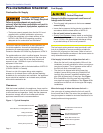
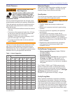
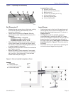
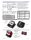
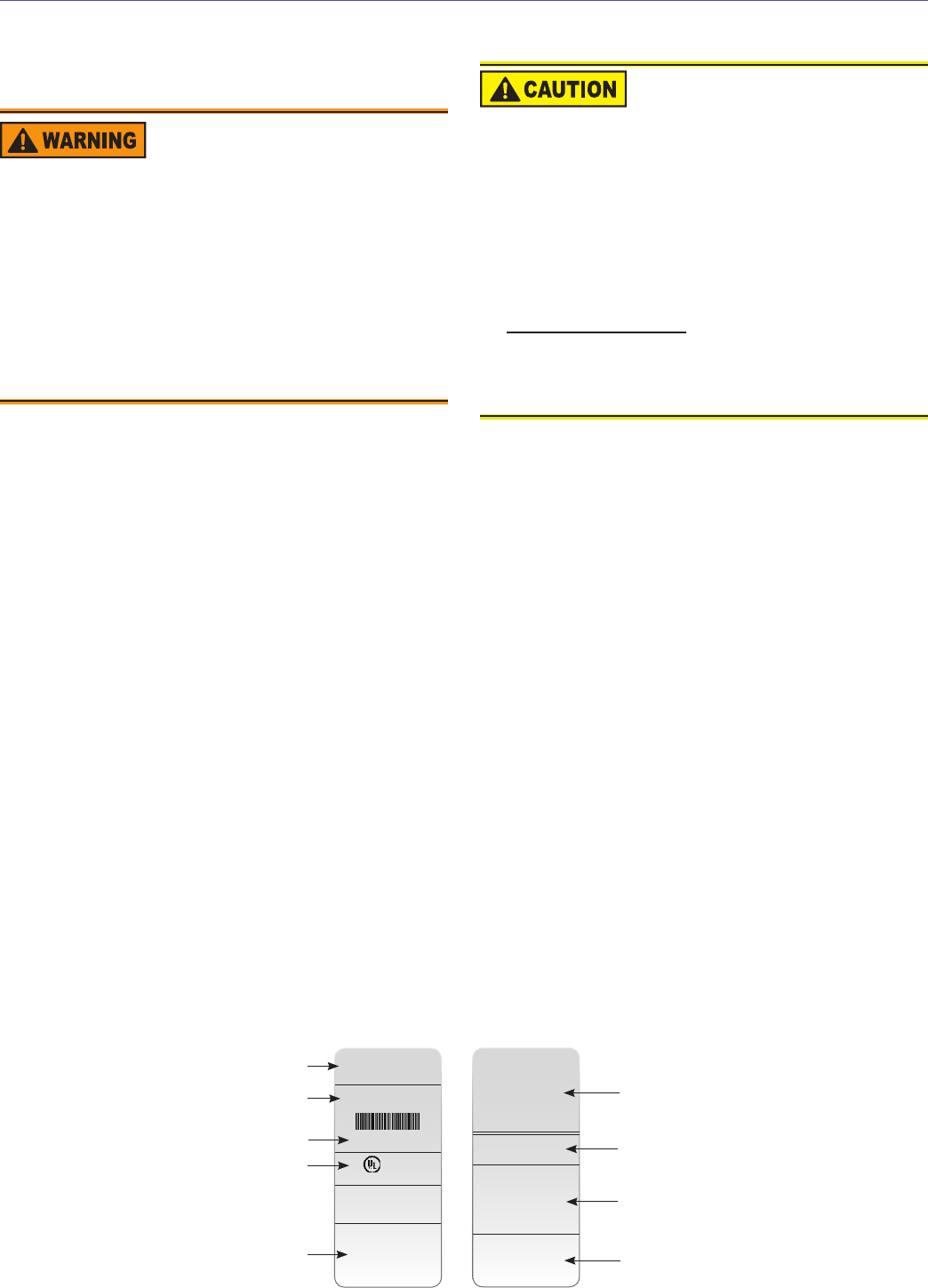
Figure 1 – Typical Nameplate
The burner requires combustion air and ventilation air
for reliable operation. Assure that the building and/or
combustion air openings comply with National Fire
Protection Standard for Oil-Burning Equipment, NFPA 31.
For appliance/burner units in confi ned spaces, the room
must have an air opening near the top of the room plus
one near the fl oor, each with a free area at least one
square inch per 1,000 Btu/hr input of all fuel burning
equipment in the room.
For other conditions, refer to the latest edition of NFPA 31
(CSA B1139-M91 in Canada).
If there is a risk of the space being under negative
pressure or of exhaust fans or other devices depleting
available air for combustion and ventilation, the appliance/
burner should be installed in an isolated room provided
with outside combustion air.
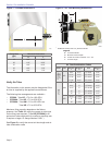
Clearances
With the burner installed in the appliance, there must be
adequate space in front of and on the sides of the burner
to allow access and operation. Verify that the clearance
dimensions comply with all local codes and with the
appliance manufacturer’s recommendations.
The fuel supply piping and tank must provide #1 or #2
fuel oil at pressure or vacuum conditions suitable for
the fuel unit (oil pump) on the burner. Refer to fuel unit
literature in the literature envelope in the burner carton to
verify allowable suction pressure.
If fuel supply is level with or higher than fuel unit —
When the fuel unit is not required to lift the oil, the
installation is usually suitable for either a one-pipe or
two-pipe oil system. The oil pressure at the inlet of
the fuel unit must not exceed 3 psig.
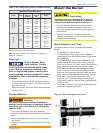
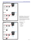
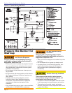
The fuel unit is shipped with the by-pass plug
installed. Leave the by-pass plug installed for all
low/high fi ring burners, regardless whether one-
pipe (with by-pass loop) or two-pipe. See Figure
9 for installation of the by-pass loop required for
one-pipe fuel supply installations. See Figure 10 for
connections to the fuel unit for two-pipe fuel supply
installations.
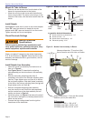
When fuel supply is below the burner fuel unit —
Use a two-pipe oil system when the fuel unit must lift
the oil more than 8 feet. The return line provided by the
two-pipe system is needed to minimize the effects of air-
related problems during operation.
○
○
Adequate Combustion and
Ventilation Air Supply Required
Failure to provide adequate air supply could
seriously affect the burner performance and result in
damage to the equipment, asphyxiation, explosion or
fi re hazards.
The burner cannot properly burn the fuel if it is not
supplied with a reliable combustion air source.
Follow the guidelines in the latest editions of the
NFPA 31 and CSA-B139 regarding providing
adequate air for combustion and ventilation.
y
y
Oil Supply Pressure
Control Required
Damage to the fi lter or pump seals could cause oil
leakage and a fi re hazard.
The oil supply inlet pressure to the burner cannot
exceed 3 psig.
Insure that a pressure limiting device is installed in
accordance with the latest edition of NFPA 31.
Do not install valves in return line.
Gravity Feed Systems: Always install an anti-siphon
valve in the oil supply line or a solenoid valve (RWB
Part # 21789) in the pump/nozzle discharge tubing
to provide backup oil fl ow cut-off protection.
y
y
y
y
Section: Pre-installation Checklist
LISTED
(FUEL) BURNER NO.P100000
SERIAL NUMBER
050214-00000
Control Circ: 120V/60Hz 4.5A
Motor Circ: 120V/60Hz 4.0A
Model “XX”
Series (Fuel) Burner
R.W. Beckett Corp.
Elyria, Ohio
Made in the U.S.A.
For use with Group 8 . . .
MP 1192 XX000 R00
X
X
X
X
X
X
XX000 R00
050214-00000
MFR’S SETTINGS
R.W. Beckett Construction &
Setting Data
R.W. Beckett Specifi cation
Number and Revision
Boiler Manufacturer and
Model, When Applicable
Additional Codes
General Model Information
Serial Number, Including Date Code
Rating Information
Approval Agency Symbols
Primary Group and Fuel