


6104 BCF35 R11 Page 15
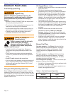
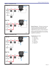
Typical Burner Sequence of Operation -
RM7897A Control
When fi ring over 20 GPH the CF2500 and CF3500A will
be supplied with a fl ame safeguard control. An airfl ow
switch and low-fi re start relay will also be supplied.
Consult local, state, and federal codes for burner
requirements above 20GPH.
Install the burner and all wiring in accordance with the
National Electrical Code and all applicable local codes or
requirements.
Wire the burner in compliance with all instructions
provided by the appliance manufacturer. Verify operation
of all controls in accordance with the appliance
manufacturer’s guidelines.
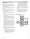
Initiate - Power is supplied to the control. The
control performs a self-check to ensure proper
operation.
Standby - the burner is idle waiting for a call for
heat. When the call for heat is initiated, the burner
will proceed to step 3.
Pre-purge - the burner will begin a 60 second pre-
purge to clear the combustion chamber. The burner
checks the air fl ow interlock to see if air is being
provided. If the air fl ow is not present the burner
will lockout if jumper JR3 is cut or recycle if the
jumper is intact.
Trial for Ignition - The RM7897A has two trial
periods. The fi rst is for light off the second is for
main fl ame establishing. The burner must see
fl ame within 10 seconds if jumper 1 is intact or 4
seconds if jumper 1 is clipped. If the fl ame is not
established, the burner will lockout if jumper 2 is
clipped or recycle if the jumper is intact. The burner
will then proceed to main fl ame establishing. If
fl ame is not sensed within 3 seconds the burner
will lockout or recycle depending on the status of
jumper 2.
Run: With a fl ame established and the control
continuing to detect a fl ame, the burner will operate
in the RUN mode until the load demand is satisfi ed
or a limit opens.
If terminals RC1 and RC2 are jumpered, the
burner operates in the Low-High-Off Mode.
The burner starts at Low, goes to High after the
fl ame stabilization period. Flame is extinguished
when the load is satisfi ed or a limit opens, and
the burner is sent to post purge.
1.
2.
3.
4.
5.
a.
If a high/low control has been wired between
terminals RC1 and RC2 the burner starts at
Low and is released to go High after the fl ame
stabilization period. It can repeatedly cycle
between low and high as necessary to meet
load demand until the load is satisfi ed or a limit
opens. The burner is then sent to post purge.
Post purge - The control enters a post purge cycle
to clear the combustion chamber of gases. Length
of the post purge is factory programmed at 15
seconds.
Cad Cell Resistance Indicator: During the burner
run state, click the reset button (less than 1 second)
to check the cad cell resistance range. The yellow
light will fl ash 1 to 4 times, depending on the
amount of light detected by the cad cell.
b.
6.
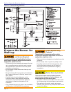
Section: Wire the Burner
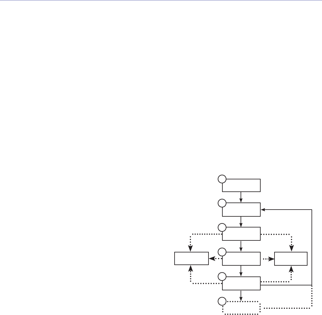
Initiate
Stand by
Prepurge
Trial for
Ignition
Post Purge
Run
1
Recycle
Lockout
2
3
4
5
6
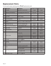
Figure 14 - Typical Burner Sequence of
Operation - RM7897A