


6104 BCF35 R11 Page 13
1
3
6
4
7
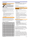
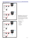
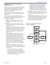
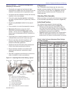
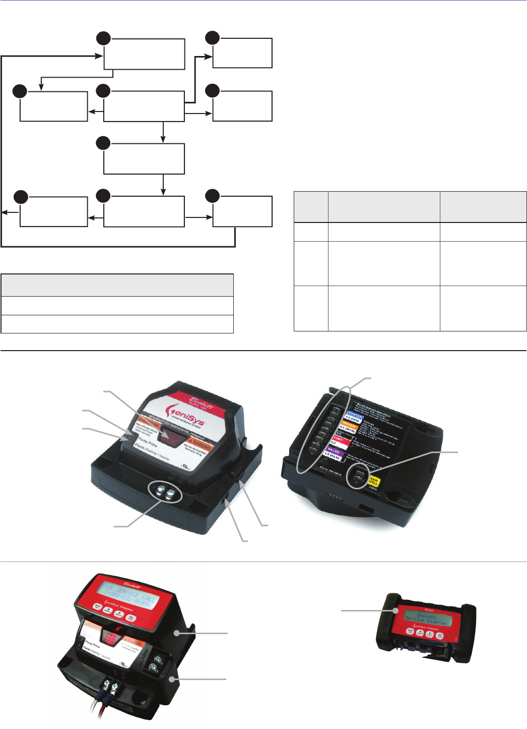
Standby
9
Pump
Prime
Valve-on
Delay
Trial for
Ignition
Lockout
Ignition
Carryover
Relight
Run
Motor-Off
Delay
5
2
8
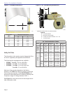
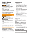
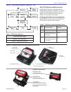
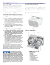
Figure 12 - GeniSys 7505 Control with Optional Components
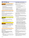
Table 5 - 7505 Status Light Explanation Table
Light
Color
On Continuously Flashing
Red Restricted (Hard) Lockout Soft Lockout
Green Flame Sensed during normal
operation (Could be stray light
during standby)
Recycle
Yellow Control is in Pump Prime mode
or Reset button currently held
for 15+ seconds.
N/A
Table 4 - 7505 Flame Detection
Flame Detection Range
Normal = 0 to 1600 ohms
Limited = 1600 ohms to lockout
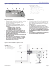
Section: Wire the Burner
Display Module:
Permanent device for
programming and diagnostics
Alarm Module:
For adding isolated low voltage
alarm contacts to the base control.
See Alarm Module Instructions for
specifi cations.
Contractor’s Tool:
Hand-held device for
programming and diagnostics
Cad Cell
Connections
Wiring
Connections
Communication Port 2
Reset Button
with Red Light
Communication Port 1
Thermostat Terminals
Green Light
Yellow Light
Optional Components:
Figure 11 - Typical Burner Sequence of Operation - 7505
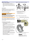
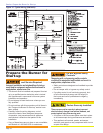
Cad Cell Resistance Measurement:
If the Beckett 7505 control is equipped with the
GeniSys Display Module, part 52067U, the cad cell
resistance can be selected and read on the LCD
screen. Also, the GeniSys Contractor Tool, part
52082U, can be used for this purpose.
If these are not available, the cad cell leads can
be unplugged from the control and the resistance
measured with a meter in the conventional way.
Conduct these tests with fl ame present.