


6104 BCF35 R11 Page 9
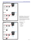
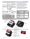
Set Dimension Z
Replace the rear access door on the burner, making
sure that the adjusting plate assembly is now
securely in the groove.
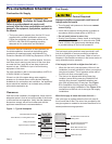
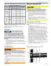
Loosen acorn nut (item d) in Figure 6. Slide the
nozzle line and plate assembly until dimension Z in
Figure 6 is:
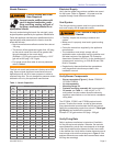
CF2500A/CF2500 = 1-3/4 ±1/16”
CF3500A (tube KM) = 2-5/8” ±1/16”
CF3500A (tube KR)= 3-9/16” ±1/16”
When dimension Z (from end of air tube to fl at area
of front face of head) is correctly set, tighten acorn
nut (item d). Verify that the adjusting plate assembly
is properly seated in the groove.
Attach the oil line from the oil valve to the nozzle line
end. Tighten securely.
Before proceeding, check dimension Z once again.
Loosen acorn nut (item d) if necessary to reposition
the nozzle line. Once dimension Z is set, do not
loosen acorn nut (item d) again.
○
○
○
○
○
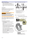
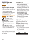
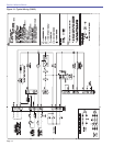
Figure 7 – Adjusting Plate Assembly
Legend (Figures 6 & 7)
a
Adjusting plate assembly
b
Spline nut for securing nozzle line
c
Bottom acorn nut
d
Top acorn nut (for setting dim. Z only)
e
Indicator adjusting plate
f
Secondary adjusting plate
g
Primary adjusting plate
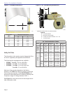
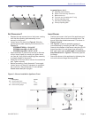
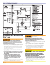
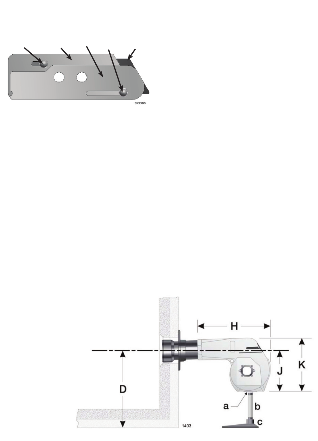
Figure 8 – Burner Installed in Appliance Front
Legend
Description Inches
H
Housing total length 20”
J
Center to bottom of housing 14-1/2”
K
Overall housing height 22-3/4”
e
f
c
g
d
Insert Burner
Position the burner in the front of the appliance and
loosely tighten the nuts on the mounting studs. The
burner should be pitched downward 2° as shown in
Figures 3 and 4.
See Figure 8. Install the pedestal support kit
(recommended) by attaching the 3/4” NPT fl ange
(item a) to the bottom of the burner using the (4) #10
screws provided. Cut and thread (one end only) a
3/4” pipe nipple (item b) with length 11 inches less
than dimension D in Figure 8. Thread the pipe into
the fl ange.
Secure the burner to the appliance by tightening the
nuts on the burner fl ange mounting studs.
○
○
○
Section: Mount the Burner