


Page 8
Mount Air Tube to Burner
Remove the rear access door from the back of the
burner for improved access to the interior.
Attach the air tube to the burner with the bolts and
acorn nuts provided. The acorn nuts must go on the
outside of the burner, with the bolts inserted from the
inside.
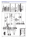
Install Nozzle
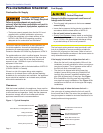
See Figure 5. Install the oil nozzle in the nozzle adapter.
Use a 3/4” open-end wrench to steady the nozzle
adapter and a 5/8” open-end wrench to turn the nozzle.
Tighten securely but do not overtighten.
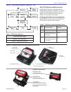
Check Electrode Settings
○
○
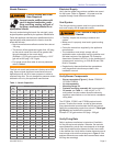
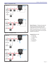
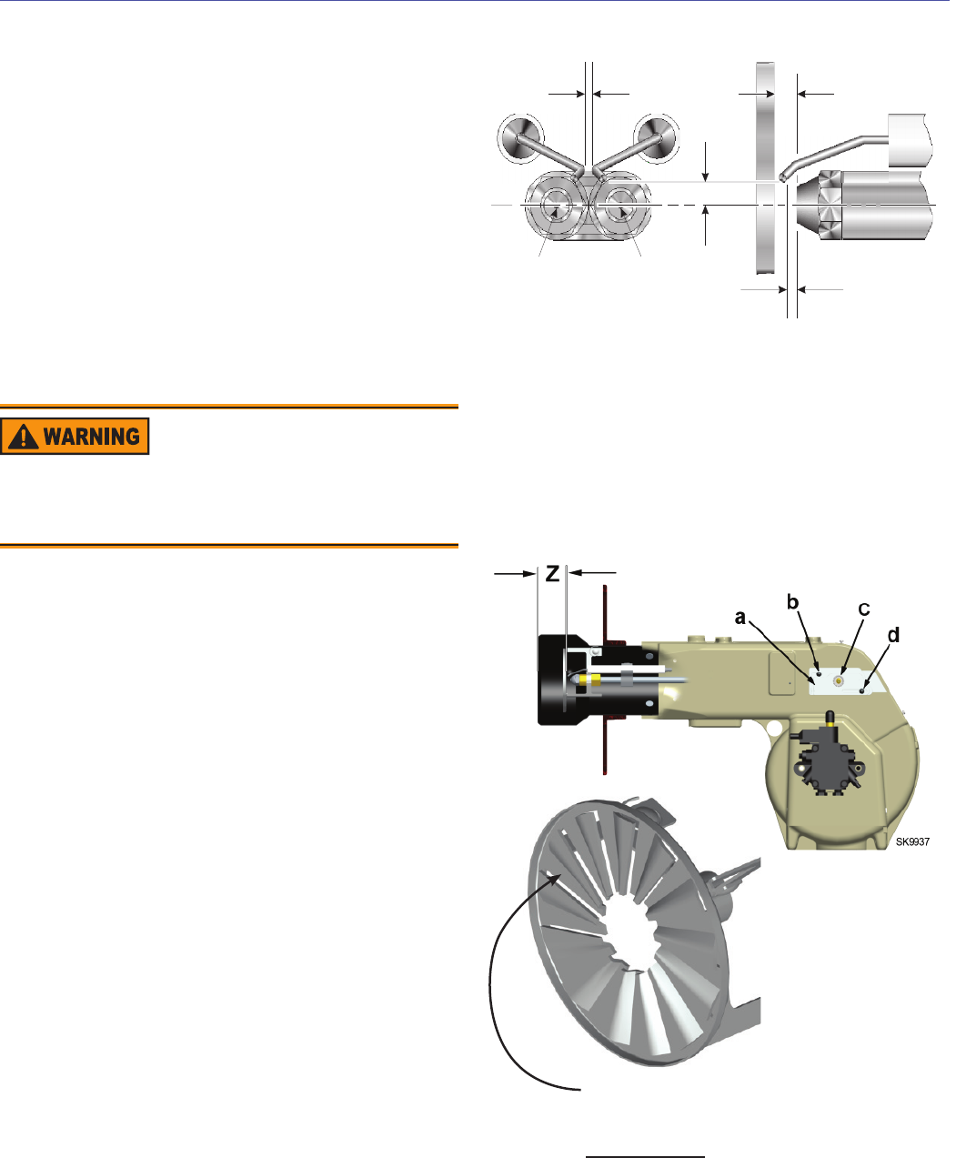
Figure 5 – Nozzle and Nozzle Line Assembly
3504
P
R
QS
Low fire
nozzle
High fire
nozzle
Legend for Critical Dimensions
P
Nozzle centerline to electrode tip - 1/4”
Q
Nozzle to head - 1/4”
R
Nozzle face to electrode tip - 1/8”
S
Electrode spacing - 3/32”
Check, and adjust if necessary, the critical dimensions
P, Q, R and S shown in Figure 5. Verify that the oil tube
assembly and electrodes are in good condition, with no
cracks or damage.
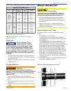
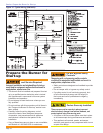
Install Nozzle Line Assembly
Insert the nozzle line assembly into the burner air
tube as in Figure 6.
See Figures 6 and 7. Assemble the adjusting
plate assembly per the instructions in the assembly
packet.
Slide the secondary adjusting plate (item f)
completely to the left on the indicator adjusting plate
(item e). Finger-tighten acorn nut (item c) to secure
the two plates together. Slide both plates completely
to the left on the primary adjusting plate (item g) and
fi nger-tighten acorn nut (item d).
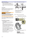
Slide the completed adjusting plate assembly
over the nozzle line end. Move the plate assembly
and the nozzle line so the plate assembly fi ts into
position as shown in Figure 6.
Install the spline nut (Figure 6, item b) on the end of
the nozzle line, leaving the nut loosely placed so the
plates can be moved.
Connect the high-voltage leads from the ignition
transformer to the electrodes.
○
○
○
○
○
○
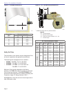
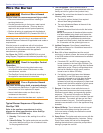
Figure 6 – Nozzle Line Assembly in Burner
Z Dimensions
CF2500A/CF2500 = 1-3/4 ±1/16”
CF3500A (tube KM) = 2-5/8” ±1/16”
CF3500A (tube KR)= 3-9/16” ±1/16”
Measure dimension ‘Z’ from front (fl at)
face of head to end of air tube, as shown.
Measure dimension ‘Z’ from the fl at surface
between (not on) the raised fi ns.
Maintain Electrode
Specifi cations
Failure to properly maintain these specifi cations could
cause ignition malfunction, puff-back of hot gases, heavy
smoke, asphyxiation, explosion and fi re hazards.
Section: Mount the Burner