


Page 2
Agency Approvals
UL listed to comply with ANSI/
UL296 and certifi ed to CSA
B140.0.
Accepted by N.Y.C. M.E.A.
Other approvals may be available
and must be specifi ed at time of
order.
○
○
○
To the Owner:
Thank you for purchasing a Beckett burner for use
with your heating appliance. Please pay attention to
the Safety Warnings contained within this instruction
manual. Keep this manual for your records and provide
it to your qualifi ed service agency for use in profes-
sionally setting up and maintaining your oil burner.
Your Beckett burner will provide years of effi cient oper-
ation if it is professionally installed and maintained by
a qualifi ed service technician. If at any time the burner
does not appear to be operating properly, immediately
contact your qualifi ed service agency for consultation.
We recommend annual inspection/service of your
oil heating system by a qualifi ed service agency.
Daily – Check the room in which your burner/ap-
pliance is installed. Make sure:
Air ventilation openings are clean and unob-
structed
Nothing is blocking burner inlet air openings
No combustible materials are stored near the
heating appliance
There are no signs of oil or water leaking around
the burner or appliance
Weekly - Check your oil tank level. Always keep
your oil tank full, especially during the summer, in
order to prevent condensation of moisture on the
inside surface of the tank.
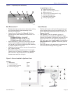
Special Requirements - The
installation of a burner shall be
in accordance with the regulations of authorities having
Jurisdiction.
For recommended installation practices in the U.S.
refer to the latest edition of NFPA 31.
(CSA-B139 and CSA-B140 in Canada.
○
Impaired Burner
Performance & Fire Hazard
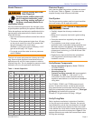
Do NOT operate the burner beyond specifi cations
outlined in the Table on Page 3.
For applications beyond these limits, consult Beckett
Technical Services at 1-800-645-2876.
NOTE: Some packaged appliances with burners
may be agency listed as a unit to operate beyond
these limits. Consult the appliance manufacturer’s
specifi cations and agency approvals for verifi cation.
y
y
Contents
General Information ....................................................3
Hazard Defi nitions .........................................................................3
Specifi cations ................................................................................3
Owner’s Responsibility: .................................................................3
Service Agency Responsibility: .....................................................3
Combustion Air Supply ..................................................................4
Clearances ....................................................................................4
Fuel Supply ...................................................................................4
Nozzle Pressure ............................................................................5
Electrical Supply ............................................................................5
Vent System ..................................................................................5
Verify Burner Components ............................................................5
Verify Firing Rate ...........................................................................5
Verify Air Tube ...............................................................................6
Dust and Moisture .........................................................................7
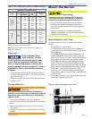
Mount the Burner .........................................................7
Mount Flange(s) on Air Tube .........................................................7
Mount Air Tube to Burner ..............................................................8
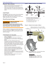
Install Nozzle .................................................................................8
Check Electrode Settings ..............................................................8
Install Nozzle Line Assembly .........................................................8
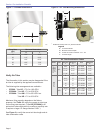
Set Dimension Z ............................................................................9
Insert Burner .................................................................................9
Connect Fuel Lines ...................................................10
Fuel Unit By-pass Plug ............................................................... 10
One-pipe Oil System By-pass Loop ...........................................10
Oil Supply/Return Lines .............................................................10
Burner Fuel Flow ........................................................................ 10
Wire the Burner .........................................................12
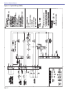
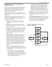
Typical Burner Sequence of Operation - GeniSys 7505 ............12
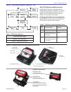
Cad Cell Resistance Measurement: ........................................... 13
Typical Burner Sequence of Operation -
RM7897A Control .........15
Z Dimension ...............................................................................17
Adjusting Plate Assembly ........................................................... 17
Initial Head Position ...................................................................17
Initial Air Settings ........................................................................ 18
Set Appliance Limit Controls ......................................................19
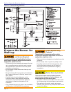
Prepare the Fuel Unit for Air Venting .......................................... 19
Start the Burner .........................................................19
Start Burner and Vent Air from Oil Line ...................................... 19
Set High-fi re Air ..........................................................................20
Set Low-fi re Air ........................................................................... 20
Perform Regular Maintenance..................................21
Annual Service — by qualifi ed service technician ...................... 21
Monthly Maintenance — by owner ............................................. 21
Replacement Parts ....................................................22