


6104 BCF35 R11 Page 5
The fuel unit nozzle port pressure is factory set at 300
psig. Some original equipment manufacturer burner
applications may call for a lower pressure to obtain a
required fi ring rate. Do not change this pressure unless
directed to do so by the appliance manufacturer.
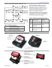
Electrical Supply
Verify that the power connections available are correct
for the burner. Refer to Figure 1. All power must be
supplied through fused disconnect switches.
Vent System
The fl ue gas venting system must be in good condition
and must comply with all applicable codes.
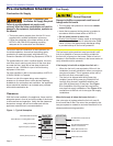
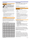
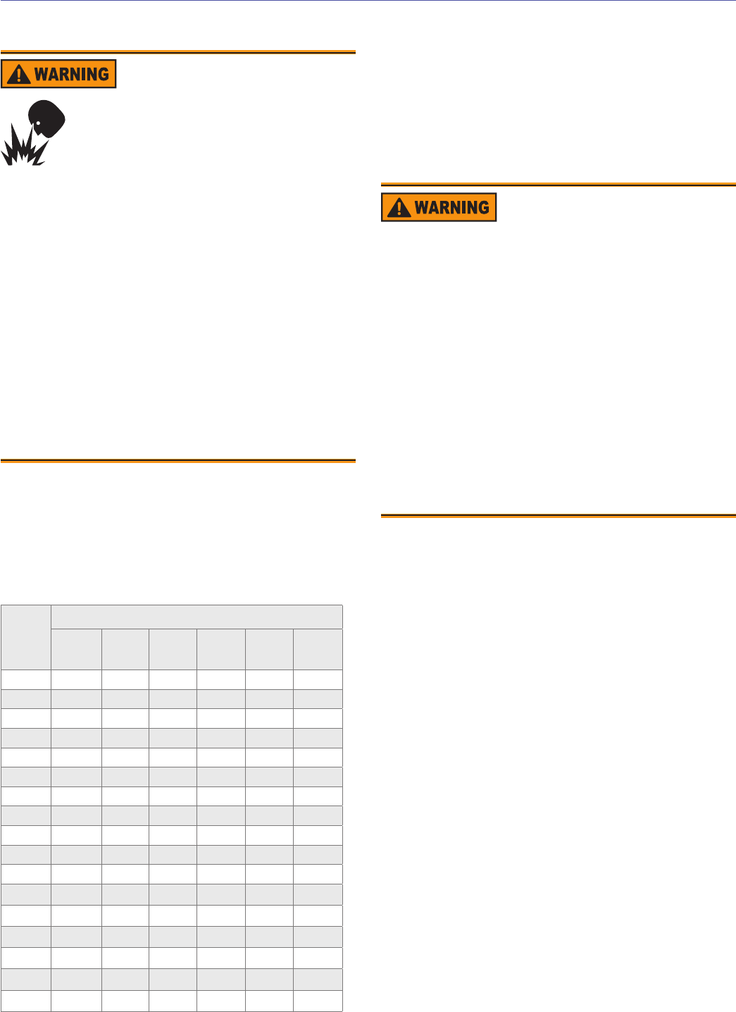
Nozzle Pressure
Table 1 - Nozzle Capacities
Rated
gph
@ 100
psig
Pressure - Pounds per square inch
125 150 175 200 250 300
5.00 5.59 6.13 6.61 7.07 7.50 8.66
5.50 6.15 6.74 7.27 7.78 8.70 9.54
6.00 6.71 7.33 7.94 8.48 9.49 10.40
6.50 7.26 7.96 8.60 9.20 10.30 11.25
7.00 7.82 8.56 9.25 9.90 11.06 12.12
7.50 8.38 9.19 9.91 10.60 11.85 13.00
8.00 8.94 9.80 10.58 11.31 12.65 13.85
8.50 9.50 10.45 11.27 12.06 13.40 14.70
9.00 10.06 11.02 11.91 12.73 14.20 15.60
9.50 10.60 11.70 12.60 13.50 15.00 16.45
10.00 11.18 12.25 13.23 14.14 15.81 17.32
10.50 11.74 12.85 13.90 14.85 16.60 18.18
11.00 12.30 13.47 14.56 15.55 17.39 19.05
12.00 13.42 14.70 15.87 16.97 18.97 20.78
12.50 13.98 15.31 16.54 17.68 19.76 21.65
13.00 14.54 15.92 17.20 18.38 20.55 22.52
13.50 15.10 16.53 17.85 19.09 21.34 23.38
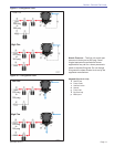
Verify Burner Components
Burner nameplate (Figure 1), Model CF2500A/
CF2500/CF3500A
Air tube assembly
Mounting fl ange kit
Pedestal mounting assembly kit (recommended)
Oil nozzle, per Table 1 — Use only 45° to 70°
solid pattern nozzles unless otherwise shown by
appliance manufacturer or on the burner nameplate
rating label.
The CF2500A, CF2500, and CF3500A are dual nozzle
burners. To select the nozzles, use half of the maximum
fi ring rate and select a nozzle under the 300 psig column.
Select the corresponding nozzle from column 1 (Rated gph
@ 100 psig) two nozzles will be required.
Example: a 5.00 gph nozzle at 300 psig = 8.66 gph
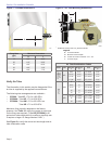
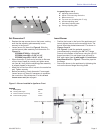
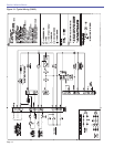
Verify Firing Rate
Refer to appliance manufacturer’s instructions (if available)
for fi ring rate and nozzle selection. Otherwise, the maximum
recommended fi ring rate for the burner depends on the length
of the fi ring chamber and the distance from the burner center
to the chamber fl oor. Verify that the chamber dimensions are at
least as large as the minimum values given in Figure 2. If the
appliance dimensions are smaller than recommended, reduce
the fi ring rate accordingly.
○
○
○
○
○
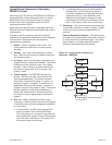
Correct Nozzle and Flow
Rate Required
Incorrect nozzles and fl ow rates could
result in impaired combustion, under-
fi ring, over-fi ring, sooting, puff-back of
hot gases, smoke and potential fi re or
asphyxiation hazards.
Use only nozzles having the brand, fl ow rate (gph), spray
angle and pattern specifi ed by the appliance manufacturer.
Follow the appliance manufacturer’s specifi cations for the
required pump outlet pressure for the nozzle, since this
affects the fl ow rate.
Nozzle manufacturers calibrate nozzle fl ow rates at
100 psig.
This burner utilizes pressures higher than 100 psig,
so the actual nozzle fl ow rate will be greater than
the gph stamped on the nozzle body.
(Example: A 12.00 gph nozzle at 200 psig = 16.97
gph and at 300 psig = 20.78 gph)
For typical nozzle fl ow rates at various pressures
refer to Table 1.
y
y
y
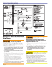
Fire, Smoke & Asphyxiation
Hazard
Carefully inspect the chimney or exhaust vent
system.
Make sure it is properly sized and in good working
condition.
Follow the instructions supplied by the appliance
manufacturer.
The installation must strictly comply with all
applicable codes, authorities having jurisdiction and
the latest revision of the National Fire Protection
Association Standard NFPA 31 for the installation of
chimneys and vent sizing, (or CSA-B139 and CSA-
B140 in Canada).
Regulation by these authorities take precedence
over the general instructions provided in this
installation manual.
y
y
y
y
y
Section: Pre-installation Checklist