


8
Form 6104 BCF10-R06
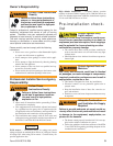
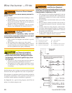
Mount the burner
Mount fl ange(s) on air tube
This section does not apply to burners with welded fl ang-
es.
Do not install air tube on burner.
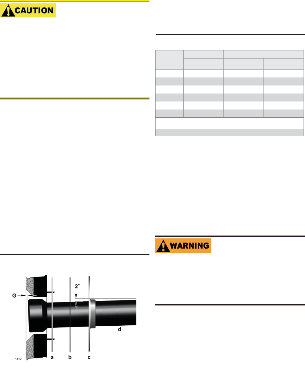
For non-pressure fi ring fl ange, refer to Figure 3: Install
gasket (item a) and fl ange (item c). Ignore the next
paragraph.
For pressure-fi ring fl ange, refer to Figure 3: Slide gasket
(item a) onto the air tube, making sure the top of the air tube
is up. Pre-drill holes in the pressure fi ring plate (item b) to
match the appliance studs. Slide the pressure fi ring plate
(item b) and fl ange (item c) onto the air tube as shown.
Wrap ceramic fi ber rope around the air tube and press
tightly into the inside diameter of the fl ange (item c).
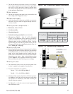
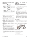
Slide the air tube (item d) into position in the appliance
front. Tighten the fl ange-mounting-stud nuts. Set the
insertion of the air tube so dimension G is 1/4” nominal.
Pitch the air tube at 2° from horizontal as shown and secure
the fl ange to the air tube.
y
y
y
y
y
y
Protect the Air Tube From
Overheating
Overheating could cause damage to the air
tube and other combustion components lead-
ing to equipment malfunction and impaired
combustion performance.
The end of the air tube must not extend into the com-
bustion chamber unprotected unless it has been factory-
tested and specifi ed by the appliance manufacturer.
Position the end of the air tube 1/4” back from fl ush with
the refractory inside entry wall to prevent damage from
overheating.
y
y
Figure 3 - Mount fl ange(s) on air tube
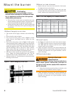
Mount air tube to burner
Remove the rear access door from the back of the burner
for improved access to the interior.
Attach the air tube to the burner with the bolts and acorn
nuts provided. The acorn nuts must go on the outside of the
burner, with the bolts inserted from the inside.
y
y
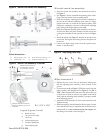
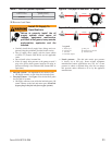
Install nozzle
See Figure 4. Install the oil nozzle in the nozzle adapter.
Use a 3/4” open-end wrench to steady the nozzle adapter
and a 5/8” open-end wrench to turn the nozzle. Tighten
securely but do not over-tighten.
Check, and adjust if necessary, the critical dimensions P,
Q, R and S shown in the drawing. Verify that the oil tube
assembly and electrodes are in good condition, with no
cracks or damage.
Check electrodes
y
y
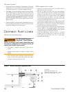
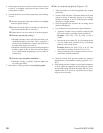
Table 2 - Air Tube Capacity vs. Firebox Pressure
Firebox
Pressure
(in. w.c.)
Tube A Tube B
10% turndown No reserve air 10% turndown
0.0
2.24 2.45 2.65
0.2
2.52 2.76 2.98
0.4
2.80 3.06 3.31
0.6
3.07 3.37 3.64
0.8
3.35 3.67 3.97
1.0
3.91 4.29 4.63
Note: 10% turndown indicates suffi cient reserve air to reduce the CO
2
in the fl ue to 90% of
its value.
Note: The above ratings may vary 5% due to variations in actual job conditions.
Adjust the electrode gap and position in relation to the
nozzle to the specifi cations shown in Figure 4.
y
Failure to properly maintain these specifi cations
could cause ignition malfunction, puff-back of
hot gases, heavy smoke, asphyxiation, explosion
and fi re hazards.
Maintain Electrode
Specifi cations
Check, and adjust if necessary, the critical dimensions P,
Q, R and S shown in the drawing. Verify that the oil tube
assembly and electrodes are in good condition, with no
cracks or damage.
y