


Form 6104 BCF10-R06
11
300 psig
300 psig
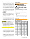
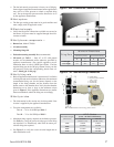
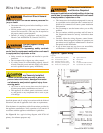
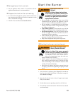
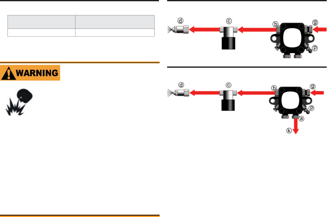
Figure 8 - One-pipe oil fl ow with “B” pump
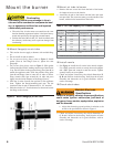
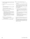
Figure 9 - Two-pipe oil fl ow with “B” pump
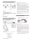
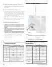
Fuel unit
model number
Gearset capacity
(gallons per hour)
B2TA8245
21
Table 3 - Fuel unit gearset capacities
Burner fuel fl ow
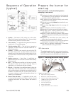
One-pipe systems – See Figure 8 for the fuel fl ow path.
Oil supply connects to one of the fuel unit inlet ports.
Two-pipe systems – See Figure 9 for the fuel fl ow paths
for two-pipe oil systems.
Oil supply connects to one of the fuel unit inlet ports. Oil
return connects to the fuel unit return port. (Install the
by-pass plug in the fuel unit for two-pipe systems.)
y
y
y
y
Carefully install the oil supply lines, fi ttings and com-
ponents using the guidelines provided in this section.
The oil supply must comply with the latest edition
of NFPA 31 (Canada CSA B139) and all applicable
codes.
Do not install valves in return line.
If the oil supply inlet pressure to the pump exceeds 3
psig or for gravity feed systems, install an oil safety or
pressure reducing valve (Webster OSV, Suntec PRV or
equivalent).
y
y
y
y
Failure to properly install the oil
supply system could cause oil
leakage, equipment malfunction,
puff-back of hot gases, heavy smoke,
asphyxiation, explosion and fi re
hazards.
Install Oil Supply To
Specifi cations
Legend
a Return port
b Nozzle port
c Oil valve
d Nozzle & adapter
g Inlet port
k Return line to oil tank
p Air bleed valve
300 psig
300 psig
Nozzle pressure – The fuel unit nozzle port pressure
is factory set at 300 psig. Some original equipment
manufacturer burner applications may call for a lower
pressure to obtain a required fi ring rate. Do not change
this pressure unless directed to do so by the appliance
manufacturer.
y