


10
Form 6104 BCF10-R06
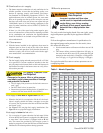
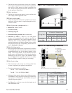
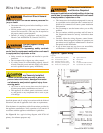
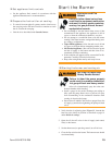
Figure 7 - Burner installed in appliance front
Legend
H Housing total length — 18”
J Center to bottom of housing — 10-7/8”
K Overall housing height — 13-3/8”
Fuel unit by-pass plug
The burner is shipped without the by-pass plug in-
stalled.
Intall the by-pass plug in two-pipe oil supply systems
ONLY.
y
y
Failure to comply could cause immediate pump
seal failure, pressurized oil leakage and the po-
tential for a fi re and injury hazard.
Do Not Install By-pass
Plug with 1-Pipe System
Use a two-pipe system, one-pipe system with by-pass
loop, or remove the by-pass plug when using with a
one-pipe system and no by-pass loop
y
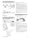
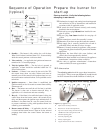
Insert burner
Position the burner in the front of the appliance and loosely
tighten the nuts on the mounting studs. The burner should
be pitched downward 2° as shown in Figures 2 and 3.
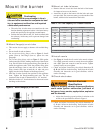
See Figure 7. Install the pedestal support kit (recommend-
ed) by attaching the ¾” NPT fl ange (item a) to the bottom
of the burner using the (4) #10 screws provided. Cut and
thread (one end only) a ¾” pipe nipple (item b) with length
10 inches less than dimension D in Figure 7. Thread the
pipe into the fl ange. Then slip the pipe end into the fl oor
fl ange (item c).
Secure the burner to the appliance by tightening the nuts on
the burner fl ange mounting studs. Then secure the pedestal
support fl oor fl ange set screw to the pipe.
y
y
y
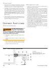
Oil supply/return lines
Install the oil tank and oil lines in accordance with all
applicable state and local codes.
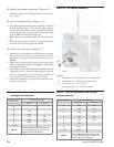
Size the oil supply and return lines using the guidelines
given in the fuel unit literature included in the literature
envelope. Oil line fl ow rate will equal the burner rate for
one-pipe systems. For two-pipe systems, refer to Table 3
for the fuel unit gear set capacity - the rate at which fuel
is recirculated when connected to a two-pipe system. Size
two-pipe oil lines based on this fl ow rate.
Use continuous lengths of heavy-wall copper tubing, routed
under the fl oor where possible. Do not attach fuel lines to
the appliance or to fl oor joists if possible. This will reduce
vibration and noise transmission problems.
Install an oil fi lter sized to handle the fuel unit gearset fl ow
capacity (Table 3) for two-pipe systems. Size the fi lter
for the fi ring rate for one-pipe systems. Locate the fi lter
immediately adjacent to the burner fuel unit.
Install two high-quality shut-off valves in accessible
locations on the oil supply line. Locate one valve close
to the tank. Locate the other valve close to the burner,
upstream of the fuel fi lter.
y
y
y
y
y
Connect Fuel Lines