


14
Form 6104 BCF10-R06
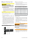
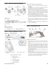
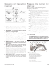
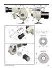
Adjusting plate assembly (Figure 11)
Make sure spline nut (item b) and bottom acorn nut (item
c) are loose.
Initial head position (Figure 11)
The indicator plate assembly (item e) markings correspond
to head position settings. Slide the secondary adjusting
plate (item f) toward the rear of the burner until the number
on the indicator plate corresponds to the initial head setting
given in Table 4 for the desired fi ring rate.
Figure 11 shows a typical example, with a head setting of
6.
When the head position has been set, tighten the bottom
acorn nut (item c) and the spline nut (item b).
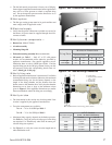
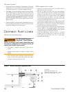
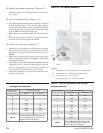
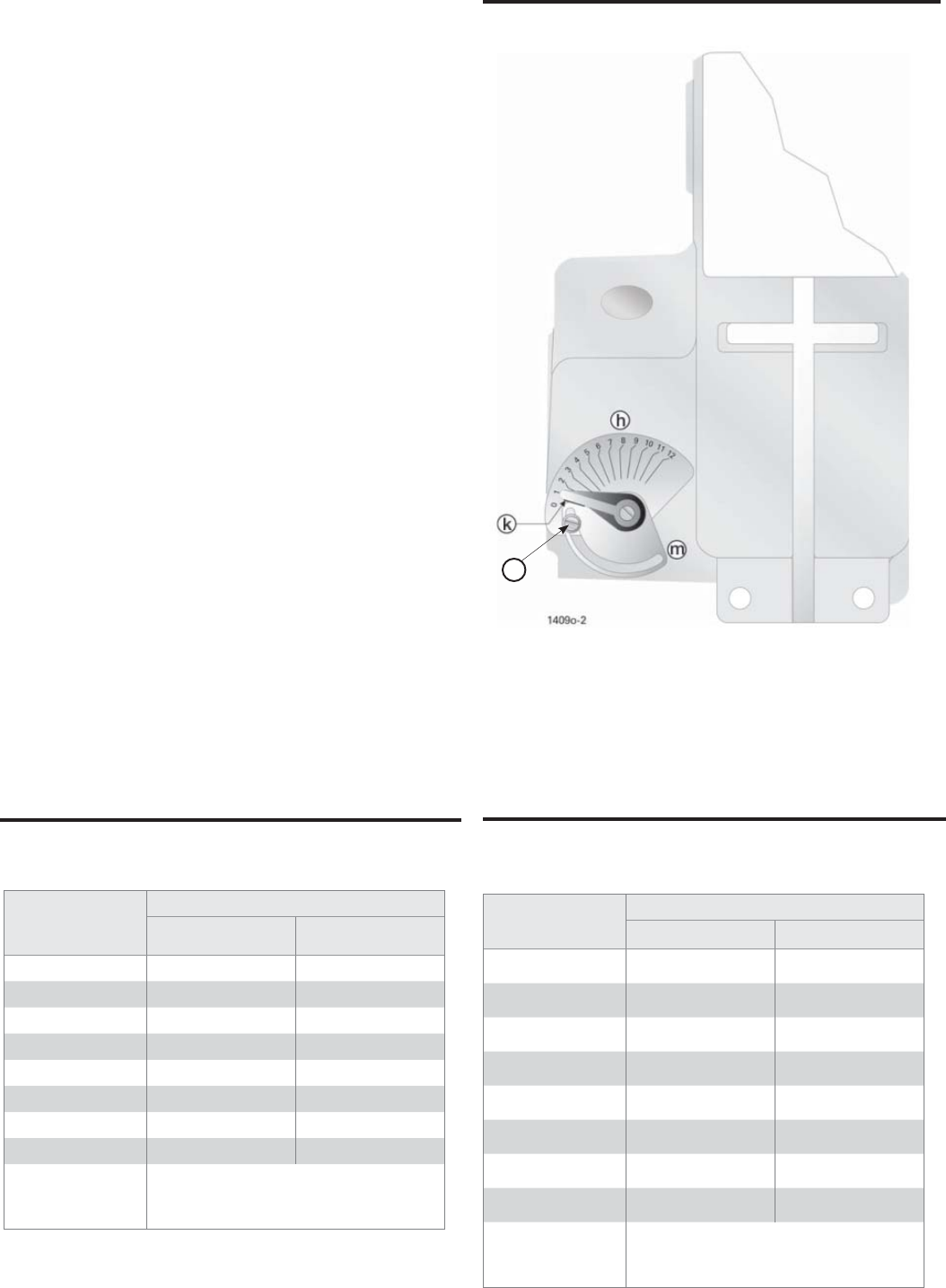
Initial air settings (Figure 12)
Loosen the screw holding the air adjusting plate (item m).
Set the air to the desired rate. (The numbers on this plate
correspond to the approximate fi ring rate settings given in
Table 5.)
Rotate the air adjusting plate until the lower edge of the
pointer is opposite the number from Table 5 corresponding
to the desired fi ring rate.
This initial setting should be adequate for starting the burner.
Tighten the screw to secure the adjusting plate. Once the
burner is in operation, the air setting will be adjusted for
best performance as discussed later in this manual.
Follow the procedures given later in this manual for fi ne-
tuning the air settings.
y
y
y
y
y
y
y
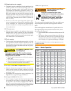
Table 4 - Initial indicator adjustment plate
settings (head position)
Approximate
adjusting
plate setting
Firing rate, gph
Tube “A” Tube “B”
0 --
1 --
2 4.00 -
3 6.00 -
4 7.00 7.00
5 8.00 8.00
6 10.00 10.00
7 - 12 --
NOTE
These settings are approximate, and
can vary depending on actual job con-
ditions and overfi re pressure.
Approximate
head settings
Firing rate, gph
Tube “A” Tube “B”
0 4.00 4.00
1 4.50 7.50
2 5.00 8.00
3 6.00 9.00
4 7.00 10.00
5 7.50 -
6 8.00 -
7 - 10 10.00 -
NOTE
These settings are approximate, and
can vary depending on actual job con-
ditions and overfi re pressure.
Table 5 - Initial air adjusting plate settings
(damper position)
Legend
h
Damper label - position indicator for air adjustment plate
k
Damper indicator - permanently attached to damper
m
Air adjusting plate - sets air position
l
Air adjusting plate screw - locks plate position
Figure 12 - Air damper assembly
l