


Form 6104 BCF10-R06
7
The fuel unit nozzle port pressure is factory set at 300 psig.
Some original equipment manufacturer burner applications
may call for a lower pressure to obtain a required fi ring
rate. Do not change this pressure unless directed to do so
by the appliance manufacturer.
Vent system
The fl ue gas venting system must be in good condition and
must comply with all applicable codes.
Electrical supply
Verify that the power connections available are correct for
the burner. All power must be supplied through fused dis-
connect switches.
Verify burner components —
Burner box, Model CF1000
Air tube assembly
Mounting fl ange kit
Pedestal mounting assembly kit (recommended)
Oil nozzle, per Table 1 — Only 45° to 70° solid pattern
nozzles are recommended unless otherwise specifi ed by
appliance manufacturer. (See specifi c appliance recom-
mendation sheet or refer to OEM Spec Guide). Find the
required fi ring rate in the 300 psig column (factory-set fuel
unit pressure). Select the corresponding nozzle from col-
umn 1 (Rated gph @ 100 psig).
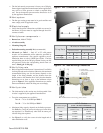
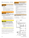
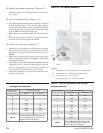
Verify fi ring rate
Refer to appliance manufacturer’s instructions (if available)
for fi ring rate and nozzle selection. Otherwise, the maximum
recommended fi ring rate for the burner depends on the
length of the fi ring chamber and the distance from the
burner center to the chamber fl oor. Verify that the chamber
dimensions are at least as large as the minimum values
given in Figure 1. If the appliance dimensions are smaller
than recommended, reduce the fi ring rate accordingly.
Verify air tube
The information in this section may be disregarded if the
air tube is supplied by the appliance manufacturer.
Two tube arrangements are available –
Tube A — 4.0 to 10.0 GPH per Table 2
Tube B — 7.0 to 10.0 GPH per Table 2
Maximum fi ring capacity depends on the fi rebox pressure.
Use Table 2 to verify the correct air tube type for the fi ring
rate required. Use Tube B only when Tube A cannot pro-
vide the fi ring rate required.
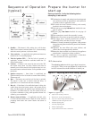
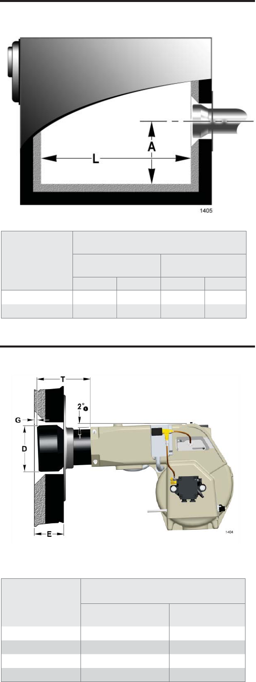
See Figure 2 to verify the correct air tube length and air
tube combination code.
y
y
y
y
y
y
y
y
y
y
y
y
y
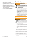
Firing Rate
Minimum Dimensions
(refractory-lined) (wet-base boilers)
ALAL
0 to 5 gph
7.0” 25.0” 7.0” 25.0”
5 to 10 gph
8.0” 35.0” 8.0” 40.0”
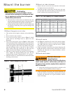
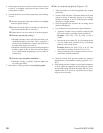
Install the burner with a 2 deg. pitch as shown
E Insertion depth
G Air tube to inside of chamber
0.25” +/- 0.125
T Air tube length
D Tube diameter
Figure 2 - Air Tube Mounting Dimensions
Figure 1. Min. Combustion Chamber Dimensions
Air Tube Length
(Dimension T)
A.T.C. Codes
(A.T.C. = Air Tube Combination)
Tube A
(Dim. D = 5-1/2”)
Tube B
(Dim. D = 5-3/4”)
06.75”
CF66KD CF66KE
10.25”
CF102KD CF102KE
13.75”
CF136KD CF136KE
17.75”
CF176KD CF176KE