


6
Form 6104 BCF10-R06
Combustion air supply
The burner requires combustion air and ventilation air for
reliable operation. Assure that the building and/or com-
bustion air openings comply with National Fire Protec-
tion Standard for Oil-Burning Equipment, NFPA 31. For
appliance/burner units in confi ned spaces, the room must
have an air opening near the top of the room plus one near
the fl oor, each with a free area at least one square inch per
1,000 Btu/hr input of all fuel burning equipment in the
room. For other conditions, refer to NFPA 31 (CSA B1139-
M91 in Canada).
If there is a risk of the space being under negative pres-
sure or of exhaust fans or other devices depleting available
air for combustion and ventilation, the appliance/burner
should be installed in an isolated room provided with out-
side combustion air.
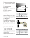
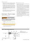
Clearances
With the burner installed in the appliance, there must be
adequate space in front of and on the sides of the burner
to allow access and operation. Verify that the clearance di-
mensions comply with all local codes and with the appli-
ance manufacturer’s recommendations.
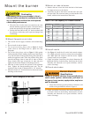
Fuel supply
The fuel supply piping and tank must provide #1 or #2 fuel
oil at pressure or vacuum conditions suitable for the fuel
unit (oil pump) on the burner. Refer to fuel unit literature in
the literature envelope in the burner carton to verify allow-
able suction pressure.
y
y
y
y
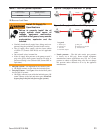
If fuel supply is level with or higher than fuel unit —
When the fuel unit is not required to lift the oil, the instal-
lation is usually suitable for either a one-pipe or two-pipe
oil system. The oil pressure at the inlet of the fuel unit must
not exceed 3 psig.
See Figure 8 for one-pipe fuel supply installations. See
Figure 9 for two-pipe fuel supply installations.
If fuel supply is below the fuel unit —
Use a two-pipe oil system when the fuel unit must lift the
oil more than 8 feet if burner is equipped with a B fuel unit,
or more than 2 feet if burner is equipped with an H fuel
unit. The return line provided by the two-pipe system is
needed to purge the air from the fuel lines and minimize the
likelihood of air-related problems during operation.
y
y
y
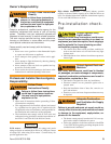
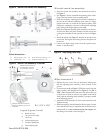
Oil Supply Pressure Con-
trol Required
Damage to the pump, fi lter or other compo-
nent seals could cause possible oil leakage
and potential fi re hazard.
The oil supply inlet pressure to the fuel unit cannot ex-
ceed 3 psig.
Do NOT install valves in return line.
Ensure that a pressure-limiting device is installed in ac-
cordance with the latest edition of the NFPA 31.
y
y
y
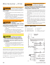
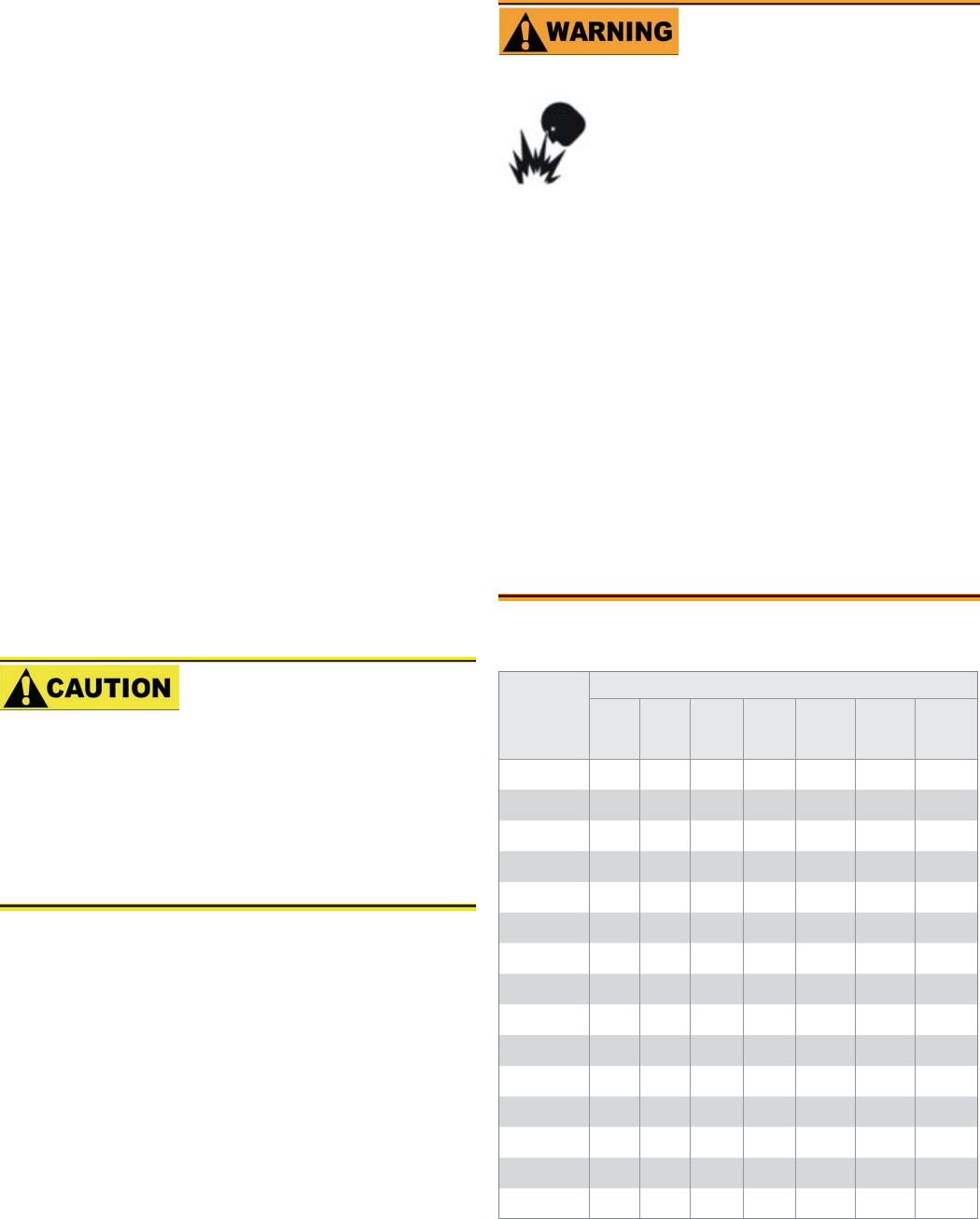
Nozzle pressure
Table 1 - Nozzle Capacities
Rated
gph
@ 100
psig
Pressure - pounds per square inch
125 150 175 200 250 275 300
2.00
2.24 2.45 2.65 2.83 3.16 3.32 3.46
2.25
2.52 2.76 2.98 3.18 3.56 3.73 3.90
2.50
2.80 3.06 3.31 3.54 3.95 4.15 4.33
2.75
3.07 3.37 3.64 3.90 4.35 4.56 4.76
3.00
3.35 3.67 3.97 4.24 4.74 4.97 5.20
3.50
3.91 4.29 4.63 4.95 5.53 5.80 6.06
4.00
4.47 4.90 5.29 5.66 6.32 6.63 6.93
4.50
5.04 5.51 5.95 6.36 7.11 7.46 7.79
5.00
5.59 6.12 6.61 7.07 7.91 8.29 8.66
5.50
6.15 6.74 7.28 7.78 8.70 9.12 9.53
6.00
6.71 7.35 7.94 8.49 9.49 9.95 10.39
6.50
7.27 7.96 8.60 9.19 10.28 10.78 11.26
7.00
7.83 8.57 9.26 9.90 11.07 11.61 12.12
7.50
8.39 9.19 9.92 10.61 11.86 12.44 12.99
8.00
8.94 9.80 10.58 11.31 12.65 13.27 13.86
Use only nozzles having the brand, fl ow rate (gph), spray
angle and pattern specifi ed by the appliance manufac-
turer.
Follow the appliance manufacturer’s specifi cations for
the required pump outlet pressure for the nozzle, since
this affects the fl ow rate.
Nozzle manufacturers calibrate nozzle fl ow rates at 100
psig.
This burner utilizes pressures higher than 100 psig, so
the actual nozzle fl ow rate will be greater than the gph
stamped on the nozzle body. (Example: A 5.00 gph noz-
zle at 150 psig = 6.12 gph and at 300 psig = 8.66 gph)
For typical nozzle fl ow rates at various pressures see ac-
companying chart.
y
y
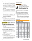
Incorrect nozzles and fl ow rates
could result in impaired combustion,
under-fi ring, over-fi ring, sooting,
puff-back of hot gases, smoke and
potential fi re or asphyxiation haz-
ards.
Correct Nozzle and Flow
Rate Required