


9
12 Vdc ADC Burner Manual
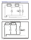
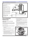
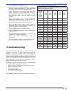
Figure 6C. Typical Wiring with 7556 Primary Safety Control
Section: Drive Component Maintenance
Drive Component
Maintenance
A. Motor, Blower Wheel, and Coupling
Replacement
The motor will require replacement if the proper voltage is
measured at the motor input, and the motor will either not
run, or the current draw with a free running pump exceeds
10% of the rated current.
To replace the burner motor, coupling and/or blower wheel
perform the following steps.
1. Before servicing, turn off and/or disconnect all power
to the burner.
2. Disconnect the burner motor wires.
3. Remove the bolts securing the motor to the burner
housing.
4. Remove the motor, coupling, and blower wheel.
5. Loosen the set screw on the blower wheel to slide
the existing wheel off the shaft.
6. Slide the new blower wheel onto the old shaft (after
thoroughly cleaning housing) and/or slide the old
blower wheel onto the new motor shaft.
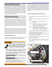
7. Place a .030” (1/32” ± 1/64”) feeler gauge between
the blower wheel and the motor housing.
8. Slide the blower wheel toward the motor until it
contacts the feeler gauge.
9. Rotate the blower wheel until the setscrew is centered
on the fl at of the motor shaft. Tighten the setscrew to
secure the wheel.
10. Slide the motor coupling on the motor shaft, then
install the motor on the burner housing. Ensure that
the motor coupling fi ts between the motor shaft and
the pump shaft inside the housing. Tighten the motor
retaining screws. Reconnect the wires.
11. Restore power, start the burner and perform
the combustion test described previously in this
manual.
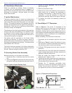
Figure 7. – Blower Wheel
Insert feeler
gauge
between
blower and
motor
Flat face on
motor shaft
Access hole
to set screw
Notes:
1. Wires are to be sized to prevent a voltage
drop between the battery and the burner with the
burner running at full load.
2. Fuse Sizes (inside control):
Motor = 30 Amp
Igniter, Control, Valve, & Alarm = 10 Amp
3. Hard-wire burner ground to battery. Do NOT
use chassis ground system.
4. Input power to the control’s +12 Volt wire shall
be provided from a fused service switch, rated at
50 amps or less.
5. Motor-off delay on a 7556P will be disabled
if the safety and operating limits as shown in
Figure 6C interrupt power to the control’s red
+12 Volt wire.
6. Do not wire power directly to the burner motor.
Only wire the motor as shown in Figure 6C. If
instant burner heat is required by the application,
purchase or program a control with a long motor-
off delay time, which will ensure instant heat if a
new call for heat is received within the motor-off
delay time.
7. Igniter Yellow leads are capped and not used.
Bundle with the other leads in the wiring box with
a cable tie.
8. The igniter Blue-White striped
and solid White leads are combined
with the 3274001 “Y” connector
and attached to the primary control
igniter spade terminal.
24V
POWER
MAIN
ALARM
VALVE
GND (VLV)
IGNITER
GND (IGN)
MOTOR
GND (MTR)
ON/OFF/RESET
HIGH
LIMIT
THERMOSTAT
OIL
VALVE
SK10089
MOTOR
IGNITER
RED WIRE
BLACK WIRE
ENABLE
CAD
CELL
CAD CELL
Note 7
Note 8