


7
12 Vdc ADC Burner Manual
For oil supply system specifi cations for tanks not mounted
on machines, carefully follow the pump manufacturer’s
literature and the latest edition of the National Fire
Protection Association (NFPA) 31 standard.
Pumps with automatic bypass do
not require a bypass plug. Verify by
referring to the pump manufacturer’s instructions.
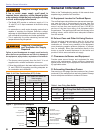
B. Fuel Supply Level with or Above Burner
The burner may be equipped with a single stage pump.
If a one-pipe system is installed, verify a bypass plug is
not installed in the pump, then connect the fuel supply
to the burner with a single supply line Note that manual
bleeding of the pump is required on initial start-up or when
the equipment runs out of fuel. When connecting a two-
pipe fuel system, install the pump bypass plug.
C. Fuel Supply Below Level of Burner
When the fuel supply is more than eight feet below the level
of the burner, a two-pipe fuel supply system is required.
Depending on the fuel line diameter and the horizontal
and vertical length, the installation may also require a
two-stage pump. Consult the fuel unit manufacturer’s
literature for lift and vacuum capability.
D. Fuel Line Replacement (Remote Tank Only)
When replacing fuel lines, continuous lengths of heavy
wall copper tubing is recommended. To ensure a tight
seal, always use fl are fi ttings. Never use compression
fi ttings. Always install fi ttings in an accessible location. To
avoid vibration noise, fuel lines should not run against the
appliance or the ceiling joists.
E. Fuel Line Valve and Filter
Shutoff valves should be located in the oil supply line. Do
not install valves in the return line.
Section: Fuel Supply
Do Not Install Bypass Plug
with 1-Pipe System
Failure to comply could cause Immediate pump seal
failure, pressurized oil leakage and the potential for
a fi re and injury hazard.
y The burner is shipped without the bypass plug installed.
y Install the bypass plug in two-pipe oil supply systems
ONLY.
Oil Supply Pressure
Control Required
Damage to the fi lter or pump seals could cause oil
leakage and a fi re hazard.
y The oil supply inlet pressure to the burner cannot
exceed 3 psig.
y Ensure that a pressure limiting device is installed in
accordance with the latest edition of NFPA 31.
y Do NOT install valves in the return line. (NFPA 31,
Chapter 8.)
y Gravity Feed Systems: Always install an anti-siphon
valve in the oil supply line or a solenoid valve (RWB
Part # 22246U) in the pump/nozzle discharge tubing
to provide backup oil fl ow cut-off protection.
Do Not Use Tefl on Tape
Damage to the pump could cause impaired burner
operation, oil leakage and appliance soot-up.
y Never use Tefl on tape on fuel oil fi ttings.
y Tape fragments can lodge in fuel line components
and fuel unit, damaging the equipment and preventing
proper operation.
y Use oil-resistant pipe sealant compounds.
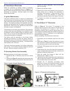
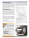
The Beckett Z gauge (part number Z-
2000) is available to permit checking
the F head “Z” dimension without removing the burner.
Fuel Supply
A. Connect Fuel Lines
Electrical Shock Hazard
Electrical shock can cause severe personal injury
or death.
y Disconnect electrical power before installing or
servicing the burner.
y Provide ground wiring to the burner, metal control
enclosures and accessories. (This may also be
required to aid proper control system operation.)
Burner Wiring
A. Burner installed on equipment
Refer to appliance manufacturer’s wiring diagram for
electrical connections.
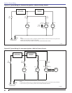
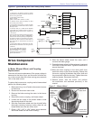
B. Burner Replacement
Burner wiring may vary, depending on the actual primary
control and furnished options. Refer to Figure 6 for typical
burner wiring, showing cad cell primary controls. Note
that the relay and control, shown in the wiring diagram
are optional features.